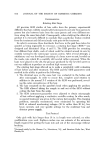
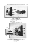
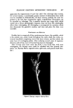
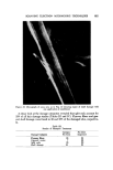
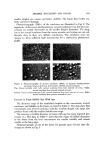
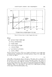
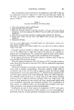
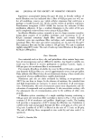
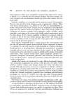
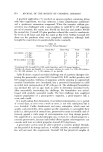
CONTINUOUS MIXING AND PROCESSING 649 The Reynolds number is: DoP Nxa• - -- - 15,033 The Darcy friction factor can be found to be (9) f =0.031 The pressure drop in an empty pipe of the same dimension can be calculated as: L pv 2 AP=fD 2g•--7'38x10 apsi Since Nng is greater than 2000, use Fig. 6 to obtain B = 2.6 at Nag ---- 15,033 Using eq 8, one obtains: K = Kov x B = 36.3 x 2.62 = 95.1 Thus, the pressure drop in the device is: APs• = K AP = 0.702 psi The theoretical horsepower can then be calculated as: Theoretical Hp = 0.262 APsu ß Q = 0.002 Hp The above two examples illustrate that only very small power consumption is required for processing both laminar and turbulent flows in the device. Contacting, and Dispersion Three forces are known to influence the formation of drops: shear stress, surface tension, and viscous stress in the dispersed phase (10). The viscous stress in the dispersed phase can be disregarded in the dispersion of fluids of low viscosities presented in this paper. When two immiscible fluids are sub- jected to the shear forces within the device, drops of one phase are produced within the other. Intimate contact between the two fluids is achieved because of the mixing characteristics of the device. Procedure Figure 9 is the schematic setup of the contacting experiment. Three sizes of the device were used in the mixer section: 1/2 in., aA in., and 1 in. inside di- ameter. Each device had glass housing with stainless steel elements. A plexi- glass chamber was built to enclose the exit section of the device. A camera was located outside the chamber to take pictures of the drops. The chamber was filled with water so that distortion of the drop size due to the curved sur-

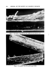
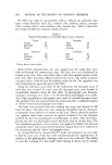
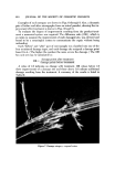
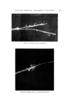
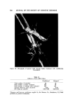
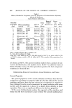
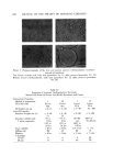
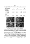
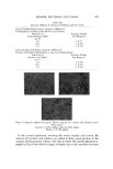
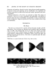
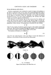
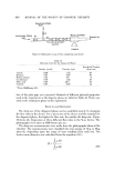
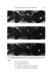
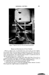
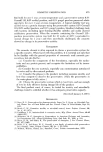
650 JOURNAL OF THE SOCIETY OF COSMETIC CHEMISTS Continuous Phase Inlet Dispersed phase Inlet Water chamber :• Dispersio LLI STATIC MIXER © section • Camera Figure 9. Schematic set-up of the contacting experiment Table II Materials Used for the Dispersed Phase" Interfacial Tension Density (g/ml) Viscosity (cps) • (dyne/cm) Anisole 0.99 1.32 26 Benzene 0.87 0.65 40 Benzyl alcohol 1.04 5.8 5 Cyclohexane 0.T8 1.02 46 Oleic acid 0.89 26.0 16 Toluene 0.87 0.59 32 From Middleman (11). face of the glass pipe was corrected. Materials of different physical properties used in the experiment as the disperse phase are listed in Table II. Water was used as the continuous phase in the experiment. }•ESULTS AND DISCUSSION The drop size of the dispersed phase can be controlled merely by changing the flow rates in the device. For a given size of the device and the material for the dispersed phase, the higher the flow rate, the smaller the drop size. Figure 10 shows the dispersions at three different flow rates in the aA-in. device. The photographs were taken at 3000 frames per sec. The drop size measurements were made from the photographs taken at the chamber. The measurements were classified into size groups of 10-/x or 50-/x intervals, depending upon the range of sizes resulting from each run. The Sauter mean diameter was calculated from the equation (10): N • ni D, a • n• D? i=1
Purchased for the exclusive use of nofirst nolast (unknown)
From: SCC Media Library & Resource Center (library.scconline.org)