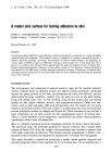
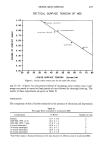
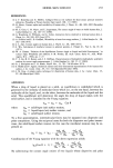
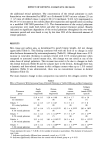
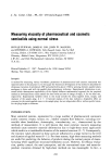
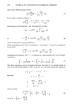
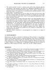
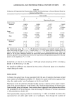
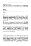
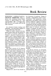
MEASURING VISCOSITY OF SEMISOLIDS 243 Syy -- - 5 YY I ' ' ! Top Plate •\• H,2 SamSpecimen r , ........ of Volume V i m I I I I I i • "' 1• Bottom ' Plate Figure I. Diagram illustrating deformation of sample plug between pressing parallel plates r -- plug radius H = plug height. q- -- •l 0 1) where T is the shear stress, i•, the shear rate, and qq, the viscosity. Shear stress. Since normal stress is used in our study, it is necessary to resolve its shear components using a three-dimensional tensor analysis (14). Based on this analysis, if normal stress, O'yy, is applied in the direction of the y-coordinate (Figure 1), then O O O S O O S,= O O 0 O'yy 0 = 0 S 0 -'[- 0 Syy 0 0 0 0 0 0 S 0 0 Stress Tensor Hydrostatic Stress where S - O + O'yy + O _ gyy 3 3 Deviatoric Stress and Syy = O'yy - S = O'yy - (O'yy) 2 3 = '•'O'yy Also, the sum of the deviatoric stress in the x, y, z direction remains zero. (2) Sxx --I- Syy -1 t- Szz = 0 (2A)

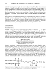
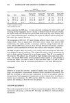
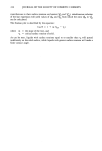
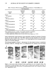
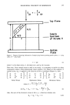
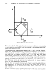
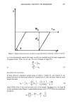
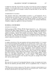
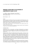
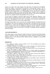
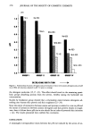
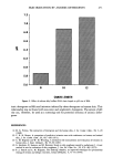
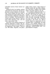
244 JOURNAL OF THE SOCIETY OF COSMETIC CHEMISTS y -Syy Sxx Sxx Figure 2. Shear stress due to normal stress. x This indicates that 2/3 of the applied normal stress is used as deviatoric stress, causing the deformation of sample shape, while the remaining • of the applied stress is ex- pended as the hydrostatic stress. This analysis provides normal deviatoric stresses in the x, y and z directions. However, in pure shear, an element experiencing a compression in one direction (y) and a tension in the perpendicular directions (x or z) (Figure 2) behaves as though it were subjected to pure shear stress •re,• on planes indicated by side "h" (15). This shear stress equals normal stress Syy in magnitude (14, 15) and causes a change in angle 0. Since no normal stress acts on side "h" of the element, the sides do not change length with deformation. Although Figure 2 represents the analysis in two dimensions, it can be shown that in a three-dimensional system, Syy splits into two equal parts in the yx and yz planes, sharing half of the magnitude in each direction. Shear rate. Shear rate is usually defined as du•/dly (Figure 3), where du• is the difference in x components of the velocities of the two layers at dly distance apart. In terms of angle 0 (Figures 1-3), the same shear rate could be defined as d0/dt with units of time -• (14,15). In a three-dimensional system, angle 0 represents only V2 of the actual strain (12), since
Purchased for the exclusive use of nofirst nolast (unknown)
From: SCC Media Library & Resource Center (library.scconline.org)