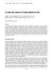
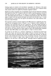
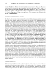
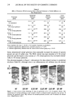
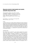
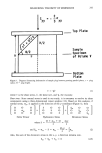
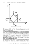
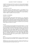
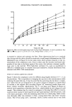
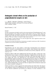
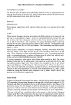
MEASURING VISCOSITY OF SEMISOLIDS 249 material was ejected and plugs of the same measured size were sliced from the middle section, with the initial and end portions discarded. Three of these plugs (used to prevent tilting of the top plate during pressing) were carefully placed on the prelubri- cated bottom plate, approximately equidistant from each other. The underside of the top plate was also prelubricated with a thin film of mineral oil. A fourth sample plug was used simply to monitor the material temperature by an Electronic Digital Ther- mometer (Fisher Scientific Co). The top plate bearing the LVDT plunger and desired weights was carefully positioned above the sample plugs with the aid of the Brookfield helipath stand (Figure 5). Actual contact of the top plate with the sample plugs at the start of the run was monitored visually and marked aproximately on the chart re- cording. The LVDT unit was precalibrated, usually at the rate of 0.04 cm/sec, or 25 sec/cm, which was equivalent to 0.0082 crrdchart division. SHAPE OF SAMPLE DEFORMATION Preliminary studies on the deformation shape of samples using PEG 1500 provided some interesting observations. After heating the material in siliconized trays (Ekco Houseware Co., IL) over a water bath to remove entrapped air, it was left undisturbed to equilibrate for a period of two weeks. The uniform cylindrical samples drawn from the congealed material were found to deform as a frustum of a cone when pressed together between the two parallel plates, with the lower end expanding faster than the upper end. Such deformation was later traced to the material's top surface rather than to Figure 5. Apparatus with accessories used to measure viscoelastic parameters. Key: (A) Main apparatus (B) Linear variable differential transformer (LVDT) unit (C) Chart recorder (D) Brookfield helipath (E) Electronic digital thermometer.

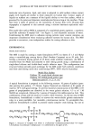
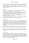
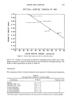
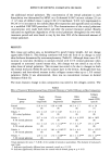
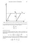
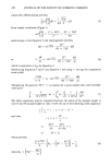
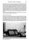
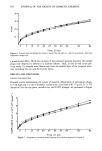
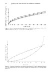
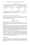
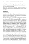
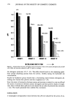
250 JOURNAL OF THE SOCIETY OF COSMETIC CHEMISTS 0.4 0.3 I i I I I , I i I I I I 2 7 12 17 22 27 32 37 42 õ2' 62 Time (t) sec Figure 6. Typical chart recordings for distance traveled by top plate vs. time for petrolatum. Each plot represents a single run. a gravitational effect. With the top layer of the prepared material removed, the sample plugs were observed to deform in a uniform fashion. Thus, in this as well as the pre- vious study (1), samples were drawn only from the middle layer of the prepared mate- rial, excluding the top and the bottom layers. RESULTS AND DISCUSSION TESTING THE EQUATION Original curves representing the extent of material deformation of petrolatum plugs, 0.7-cm high and 1.2-cm in diameter, tested with a total load of 81.31 g (23.51 X 10³ dynes/cm 2) for the top plate, metallic rod, and LVDT plunger, are presented in Figure E o 3 z 2 7 12 17 22 27 32 7 42 52 Time (t} sec Figure 7. Compliance calculated using Equation 8 oeor the data depicted in Figure 6.
Purchased for the exclusive use of nofirst nolast (unknown)
From: SCC Media Library & Resource Center (library.scconline.org)