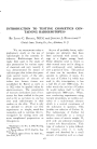
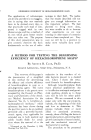
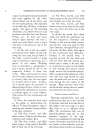
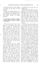
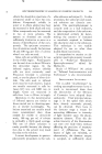
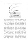
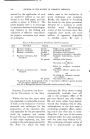
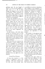
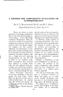
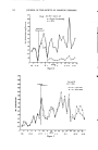
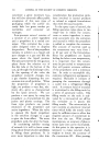
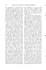
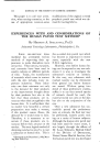
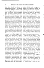
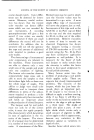
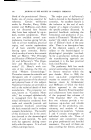
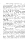
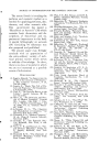
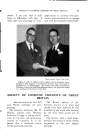
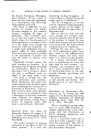
COMPARATIVE EVALUATION OF ANTIPERSPIRANTS 309 Perspiration( •Gases /Respiratory _ •" x, x Perspiration--•, •, •. WaterN / •..Gases / Cutaneous X, Perspiration"• •.,. / '"•W a t er .... X,dnsensible /Perspiration / -Sensible Perspiration that while Kuno studied perspi- ration and its production on all parts of the body under various stimuli he does not appear to have interested himself in methods of suppressing or reducing it.) Chiefly for the sake of convenience most of the comparison work with this apparatus was done using the inner surface of the forearm as a test area, but with a modification of the cup design the apparatus can be and has been used on the axilla. Further, experimental subjects who have never used antiperspirants on the forearms are much easier to find than those who have never used antiperspirants on the axilla. Essentially this method is to clamp a snugly fitting metal cup on the skin area to be studied and to pass a current of dried air over the enclosed skin surface and through a rated U-tube containing indicating Drierire. The gain in weight of the U-tube is the measure of the moisture given off by the test area. The rate of perspiration (At) Air intake. (B) Double stopcock. (½) Drying Tower (filled with indicating Drier- ire) (D) Pressure regulator con- taining water. (E) Flowmeter. (F) Indicating Drierire- filled U-tube, weighed before and after each run. (G) By-pass. (H') 3-way stopcock. (K) Stainless steel cup with inlet and outlet tubes strapped or clamped on forearm. PUMP Figure 1

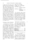
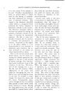
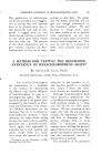
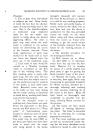
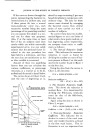
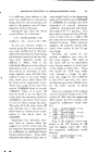
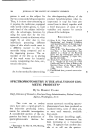
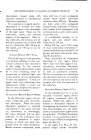
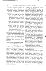
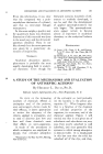
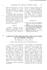
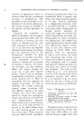
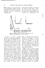
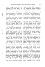
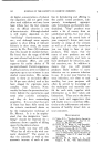
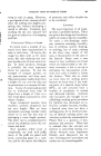
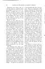
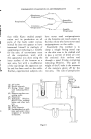
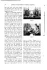
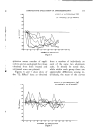
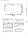
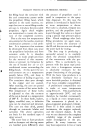
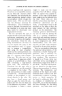
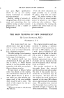
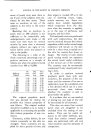
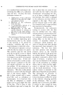
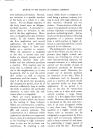
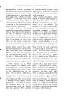
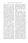
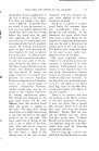
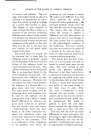
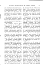
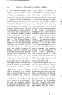
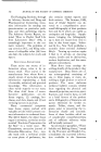
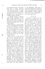
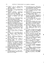
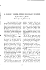
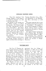
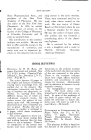
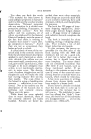
310 JOURNAL OF THE SOCIETY OF COSMETIC CHEMISTS flow per unit area may readily be calculated from the total area enclosed by the cup and the time- length of the run. Figure 1 is a schematic diagram of the apparatus for a single arm. Air from the room is drawn in through tube ,4 and is dried as it passes through drying tower C. The dry air is than drawn into the stainless steel arm cup K and over the test area of the skin and into the 3-way stopcock H where the air may be directed through the by-pass G or the tared U-tube F. The by- pass is useful for preliminary sweep- ing of the test area. The air is drawn further through a calibrated gas flowmeter E at the rate of about 1 liter per minute into cylinder D which is a water column pressure regulator anti then on through the stopcock B to the vacuum pump. The double stopcock (.d-B) should be noted by which intake and outlet may be cut off simulta- neously, leaving a partial wtcuum in the system. Leaks anywhere in the system may be detected by cutting off this double stopcock and watching for any rise of water in the safety tube of cylinder D. The apparatus works equally well by using an airstream under pres- sure, but such an arrangement is more conducive to leakage around the cup edges. In the arrangement described here the partial vacuum acts to minimize leakage. These apparatuses were used in pairs in order to make simulta- neous measurements on correspond- ing areas of the subject's two fi)re- i.. -7--"'..:' .5 ..... ß . : • • •..:7.. ....... .,i ß •, ..• :-• .i •... Figure 2 Figure 3 arms or axillae. Figure 2 is a photograph of the dual apparatus and Fig. 3 shows it in use. The cup ends are curved to fit the fi•re- arm and the cups shown here covered a skin area of approximately 42 sq. cm. each. The procedure used was to have the subject stay fi•r thirty to forty- five minutes in a roonq maintained at 105 to 110 ø F. and at 30 to 35 per cent relative humidity. This accli- matization time is necessary to initiate thermal sweating. The cups were then clamped on the subject's forearms, the apparatus was tested for leaks and the air flow, adjusted to a flow rate of 1 to 2 liters per
Purchased for the exclusive use of nofirst nolast (unknown)
From: SCC Media Library & Resource Center (library.scconline.org)