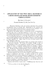
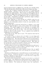
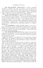
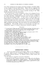
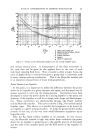
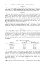
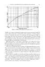
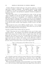
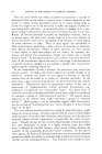
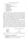
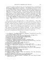
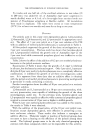
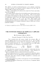
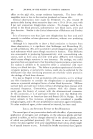
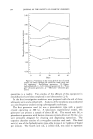
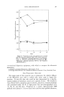
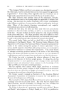
260 JOURNAL OF THE SOCIETY OF COSMETIC CHEMISTS I i I I I F'•_L..r-'I L_j L--.,I I 1 Figure 1.--Scale up from small laboratory tank to larger volume keeping all fluid ratios identical. tank. Practically all mixing processes are scaled up successfully, since the exact numerical ratio between all of the quantities is not as important as the gross over-all mixing effect. However, if one or two of the quantities listed previously are important, then we must be sure to maintain those quantities in their proper numerical value and let the other quantities fall where they will. However, scale-up can be most accurate when the major controlling factors in the process are known, since we may then control accurately the quantities that are most important. ß FLUID FORCES In many texts on scale-up of hydraulic processes, the concept of fluid forces is used. In a mix- ing process, the use of these fluid force concepts is helpful in estab- lishing the fluid flow pattern through the system, and the power consumed by a mixing impeller, but it does not define the process performance of the system. The force we apply to the liquid in the tank is related to the speed and diameter of the impeller. This is the force that we control by our choice of the mixer. The fluid in the tank has several in- ternal forces which resist move- ment of the fluid. These are viscous force, gravitational force, Figure 2.--Scale up to larger volume using single larger mixer. Mixing ratios not identical.

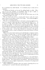
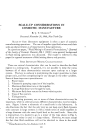
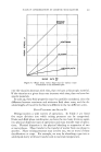
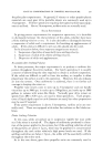
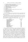
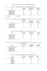
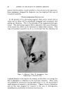
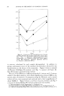
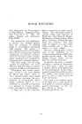
SCALE-UP CONSIDERATIONS IN COSMETIC MANUFACTURE 261 ri-t----,_•i•, r• Iz-- -•-'.•.,:r .... -i-' : F,,F-W-, C• !:11 '--[-l, TIq•,r .... /- •-['.'Fr ! ,•-••,--:T :-'r • .... t'l-rr? ,., ' --'hOE'-TURB•N E- BA FF LED •',1 / • I•!•"• I . *!!Ill' I I I!1•'!. : , : I,,, ,' , , I-FFi ' I • , i I i ! I , ,•,,' I I I !i',!' i:i•- 5---½_-•2 i_ •. .6_-•-_--_•=t• e::_ _•_ ._• '"'•A FFL ED-OR- •FF CENTER ß ": ! !•'il.11 ' :' 'H• Ill,l:. •-:.'--' -r--'--l-?, i ---'.'---•- '[41" ----t- '?.:,rl- '' ' :i : I I '1 • 5 • • 5 I0 $ 10 4 I0 5 10 6 D IMPELLER DIAMETER N IMPELLER ROTATIONAL SPEED •' LIQUID DENSITY JJ. LIQUID VISCOSITY P POWER g GRAVITY CONSTANT Figure 3.-•Power number Reynolds number curve for several impeller types. and surface tension force. A measurement of the fluid movement in the tank then can be given by the applied force to the sum of each individual resisting fluid force. Since viscosity is often a major force, the ratio of applied force to viscous force gives a group that is commonly used in many mixing scale-up correlations. This is the Reynolds number and is an important characteristic of many mixing operations. Power Drawn by an Impeller At this point, it is important to define the difference between the power drawn by an impeller at a given diameter and speed, and the speed and di- ameter required to carry out the mixing process. Correlations have been developed to relate the power drawn by a mixing impeller to the speed and diameter of the impeller as well as its shape, tank shape and fluid proper- ties. These correlations use dimensionless groups--the Power number and the Reynolds number. Th•s curve is shown in Fig. 3 for several typical impeller types. This allows us to predict the horsepower to be drawn by an impeller in a given mixing situation. It holds for geometrically similar systems of any size, all the way from small laboratory equipment up to large plant size. Take the fiat blade turbine impeller as an example. In low viscosi- ties, the Reynolds number is high and under these conditions the power drawn by an impeller is proportional to the specific gravity of the liquid and the cube of the impeller speed and the fifth power of the impeller di- ameter.
Purchased for the exclusive use of nofirst nolast (unknown)
From: SCC Media Library & Resource Center (library.scconline.org)