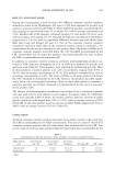
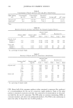
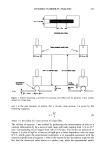
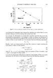
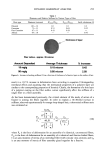
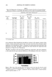
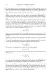
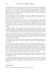
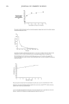
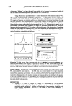
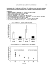
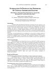
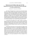
DYNAMIC HAIRSPRAY ANALYSIS 2 5 5 Table I Diameters and Relative Stiffness for Various Types of Hair Hair type Diameter (microns) (Porie,•t/P)•,,p_ Pori•,•t/P)theo•. Swift calculation (2) Oriental 101 + 14 1.0 1.0 1.0 Caucasian 72 + 11 0.51 0.63 0.35 Fine Caucasian 67 + II 0.43 0.59 -- African 64 + 10 -- 0.76 fiber radius - approx. 35 micron Amount Deposited Average Thickness thickness of layer % Increase 15 mglg 0.15 micron 0.42 90 mglg 0.90 micron 2.58 Figure 6. Increase in bending stiffness (%) as a function of thickness of a fixative layer on the surface of hair. result in a 10.7% increase in deformation force according to equation 9 (disregarding interfacial effects and assuming that the mechanical properties of a polymer layer are similar to the corresponding properties of keratin). Clearly, the formation of a thin layer of a polymer coating on the fiber surface cannot significantly affect the stiffness of a single fiber or a fiber assembly. As has been demonstrated previously, the critical element of the mode of action of a fixative is joining the fibers together. In order to explain a 10-30-fold increase in stiffness, observed experimentally for omega-loop-shaped hair, a theoretical stiffness ratio was estimated as: •yEI,l -) P,,1 R3 'rr 1 -- P. - nSyEI I nl I nl (lO) where Pn is the force of deformation for an assembly of n identical, unconnected fibers, Pnl is the force of deformation for an assembly of n identical and fixative-linked fibers, I is an area moment of inertia of an individual fiber (with circular cross section), and Inl is an area moment of inertia of fiber assembly glued together by a fixative.

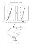
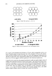
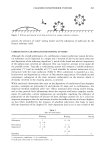
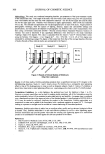
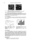
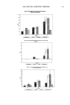
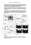
256 JOURNAL OF COSMETIC SCIENCE The values of In• and theoretical stiffness ratios (P•/P.) were calculated for several model fiber assemblies by using the parallel-axis theorem (see Appendix) (6). The results of calculations for simple models are shown in Figure 7. Figure 7a shows that linking two fibers, side by side, horizontally at a 0 ø angle to the center of gravity axis, with the bending force acting vertically, does not result in an increased stiffness of the assembly. The system behaves as if the fibers were not linked together, and consequently, the calculated stiffness ratio is equal to t. On the other hand, linking of the fibers at a 90 ø angle (characteristic for packing in a cubic lattice) to the center of gravity axis, as shown in Figure 7b, results in stiffening of the system and a calculated stiffness ratio equal to 5. Also, linking the fibers at a 60 ø angle (characteristic for packing in a hexagonal lattice) results in a stiffness ratio of 4. Schemes of model cubic and hexagonal lattices are shown in Figure 8. An assembly of four fibers arranged on a cubic lattice has a stiffness ratio of 5, the same as calculated for two fibers at a 90 ø angle. Clearly, the fibers linked at a 0 ø angle do not contribute to an increase in the stiffness ratio. Figure 7c shows the arrangements of three and four fibers linked at 90 ø and the corresponding stiffness ratios that rapidly increase with the number of fibers. Based on the analysis of model systems containing a small number of fibers, general equations can be derived connecting the stiffness ratio and number of fiber layers (for derivation, see Appendix): For cubic lattice and even n P,/ 2 •.• +(2N-1)2q'rr 4 P, n• r 4 For cubic lattice and odd n -- 3 r/ q'l'r Z 4 -- + 2 (n - 1)2 q'rr P,z 4 3 P, n'rr r 4 For a hexagonal lattice and even n (11) (12) N=n/2 [ qT r 4 P,/ 2 •.• k •- +0'75(2N- 1) 2.rr r 4 P, - n•r r 4 (13) 2 where n is the total number of fiber layers. Equations 11, 12, and 13 for an even and odd number of layers on a cubic lattice as well as for an even number of layers on a hexagonal lattice are plotted in Figure 9, which shows a fast increase in stiffness ratio as a function of the number of layers for both cubic and hexagonal models of fiber packing in a bundle. An increase for the hexagonal model is less than for the cubic lattice as a result of a slower buildup in bundle thickness. Considering the dimensions and weight of a tress used in experiments (section between plastic tabs: 3.8 cm length, 1.0 cm width, and 0.2 G), and assuming a fiber density
Purchased for the exclusive use of nofirst nolast (unknown)
From: SCC Media Library & Resource Center (library.scconline.org)