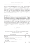
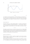
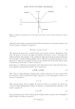
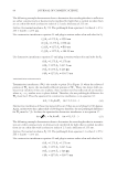
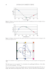
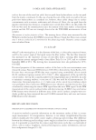
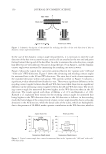
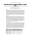
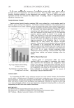
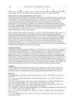
J. Cosmet. Sci., 61, 85–105 (March/April 2010) 85 Basic optics of effect materials STEVEN A. JONES, BASF Corporation, 540 White Plains Road, Tarrytown, NY 10591. Accepted for publication August 24, 2009. Synopsis Effect materials derive their color and effect primarily from thin-fi lm interference. Effect materials have evolved over the decades from simple guanine crystals to the complex multilayer optical structures of today. The development of new complex effect materials requires an understanding of the optics of effect materials. Such an understanding would also benefi t the cosmetic formulator as these new effect materials are intro- duced. The root of this understanding begins with basic optics. This paper covers the nature of light, inter- ference of waves, thin-fi lm interference, color from interference, and color travel. INTRODUCTION Classical color pigments produce color by absorbing select bands of the visible spec- trum. The remaining wavelengths are diffusely refl ected (scattered) and combine to produce a color. Many effect materials, on the other hand, derive their color from thin fi lm interference. Examples of products that contain thin fi lms include mica and boro- silicate fl akes coated with TiO2 and/or Fe2O3, and more recently with multilayer stacks such as TiO2/SiO2/TiO2. As a result of refl ection and refraction of light on a thin fi lm, certain wavelengths are removed by destructive interference while others are enhanced by constructive interference. This paper provides an understanding of how light interacts with a thin fi lm to create interference and how color is derived from that interference. NATURE OF LIGHT LIGHT AS A WAVE In physics class, we are taught about the dual nature of light, sometimes being consid- ered a particle and at other times a wave. For the purposes of thin fi lm interference, light is considered to be a wave as depicted in Figure 1. A wave has a wavelength λ, which is the length of a repeating unit (m) shown in Figure 1, a velocity v, which is the speed of the wave in a medium (m/s), and a frequency ν, which is the number of waves that pass per unit of time (s-1 or Hz). Wavelength, velocity, and frequency are related by equation 1:

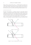
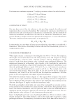
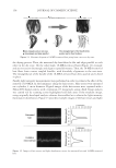
JOURNAL OF COSMETIC SCIENCE 86 = Qλ v (1) It is important to note that the frequency is fi xed by the light source and remains con- stant. Also note that wavelength and velocity are directly proportional and that wave- length and frequency are inversely proportional at constant velocity. For a wave traveling in a vacuum or in air (close enough to a vacuum), the velocity is c, and the speed of light, 3 × 10⁸ m/s. INDEX OF REFRACTION The index of refraction is a unitless complex number (n + ik), where k is the absorption coeffi cient. For transparent, non-absorbing materials, k = 0 and the refractive index re- duces to the simpler and more familiar n. The refractive index of a medium is defi ned as the speed of light in a vacuum divided by the velocity of light in the medium, as in equa- tion 2: n c v = / (2) The higher the index of refraction of a material, the slower the velocity of light through the material. The refractive index of a material is also dependent on the wavelength of the light. For white light, which contains many wavelengths, this phenomenon is referred to as dispersion. Therefore, tables of refractive indexes list values for one wavelength, com- monly 589.3 nm, also referred to as the sodium D line. REFLECTION AND REFRACTION When light travels in a medium, it travels in a straight line until it hits an interface, defi ned as a change in the refractive index. At the interface, some of the light is refl ected and some is refracted (see Figure 2). The law of refl ection states that the incident angle relative to the normal, θ1, is equal to the refl ected angle, θ1′. This refl ection is specular. If the refl ection is at an interface where n2 n1, the refl ected wave has a phase shift of 180 degrees. The percentage of light Figure 1. A light wave of wavelength λ.
Purchased for the exclusive use of nofirst nolast (unknown)
From: SCC Media Library & Resource Center (library.scconline.org)