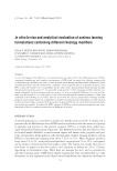
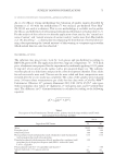
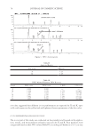
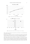
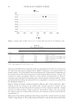
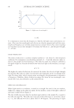
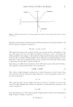
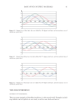
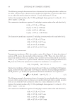
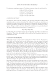
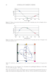
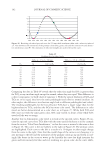
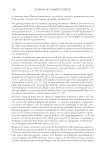
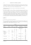
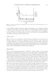
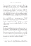
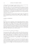
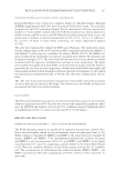
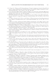
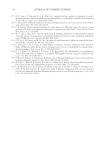
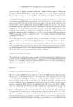
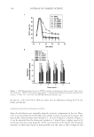
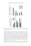
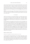
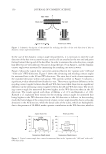
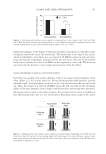
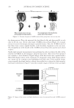
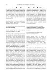
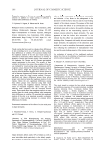
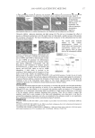
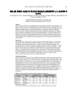
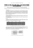
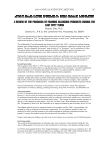
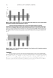
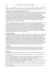
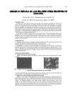
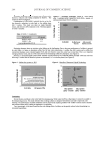
BASIC OPTICS OF EFFECT MATERIALS 91 THIN-FILM INTERFERENCE GEOMETRY OF INTERFERENCE There are many examples of thin-fi lm interference in the natural world. Examples include soap bubbles and oil spilled on a wet road, as well as some birds and insects. Figure 11. Original wave (blue line), the wave shifted by 135 degrees (red line), and the resultant wave of interference (green line). Figure 12. Original wave (blue line), the wave shifted by 180 degrees (red line), and the resultant wave of interference (green line). Figure 10. Original wave (blue line), the wave shifted by 90 degrees (red line), and the resultant wave of interference (green line).

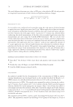
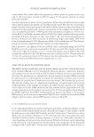
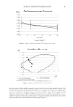
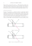
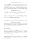
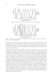
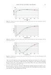
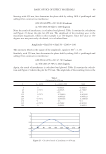
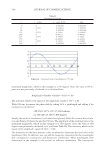
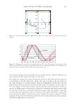
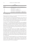
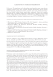
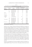
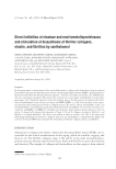
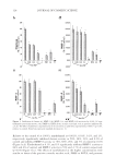
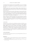
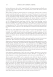
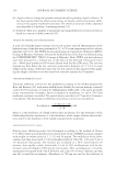
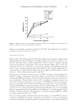
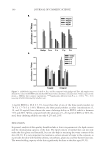
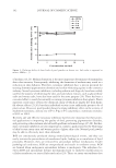
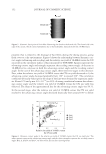
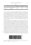
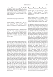
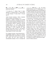
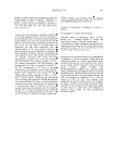
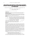
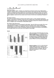
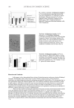
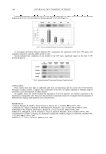
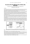
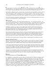
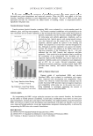
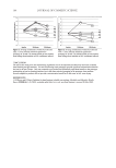
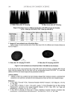
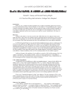
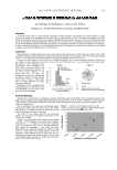
JOURNAL OF COSMETIC SCIENCE 92 Figure 13 depicts a typical thin fi lm, where n1 n2. When light shines on the fi lm, some of the light is refl ected off the top surface and the rest of the light is refracted down into the fi lm. When the light reaches the bottom interface of the fi lm, some of the light is refl ected back up. The rest of the light exits the fi lm. When light waves that were re- fl ected from the top meet the waves that traveled through the fi lm, interference occurs. PATHLENGTH AND PHASE SHIFT The nature of the interference, i.e. constructive, destructive, or some degree of partial interference, is determined by the phase shift of the waves. The phase shift of the two interfering waves is determined by the pathlength difference, which means how much farther did the shifted wave travel to get to the point of interference compared to the other. With a fi rst glance at Figure 13, one might assume that the pathlength difference is equal to the distance that W I1 traveled in the fi lm. However, this is not correct. Figure 14 depicts the geometry of the pathlength difference in the thin fi lm. The two incident waves, W I1 and W I2 , are parallel and in phase up to the point where W I1 is at point Figure 13. Thin-fi lm interference. Figure 14. Geometry of pathlength difference in a thin fi lm.
Purchased for the exclusive use of nofirst nolast (unknown)
From: SCC Media Library & Resource Center (library.scconline.org)