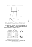
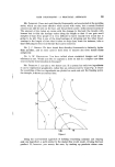
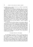
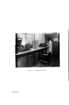
ASPECTS OF LABORATORY PLANNING 43 beams of considerable depth. In turn, this had some effect on the height of the laboratories. In the main laboratories the finished floor to ceiling height is 10 ft 6 in. Because of the dimensions of the smaller rooms it is a foot less, 9 ft 6 in, and the additional ceiling void is available for extract ducting to fume cupboards in these laboratories. The superimposed floor loadings In considering the superimposed load factor to be allowed for in the structural design, it was relatively easy to designate our existing equipment loading. However, even in these days of space-travel and miniaturization, one never can be certain that some new technique will not be developed which will require floors of very high load bearing capacity. We therefore decided to agree upon the realistic super-imposed floor loading of 1 cwt/sq. ft and the structure of the laboratory building has been designed accordingly. Structure of the building Our civil engineering department considered that these requirements of the laboratory would be met satisfactorily by a steel-framed building. The external structural members of the steelwork were to be clad with concrete to provide protection from fire and corrosion. Precast concrete units were planned for the floors with slotted units to be installed on a modular basis to provide access from the laboratories to the services. Space heating and air conditioning Most space heating systems occupy quite a large amount of space within a building, either for individual heating units or for ducts where plenum systems are involved. In a building such as a laboratory where the density of services is high, it is most desirable from an economic viewpoint that any heating system should not occupy useful and costly laboratory space. With this in mind, and wishing also to preserve as much internal planning flexibility as possible, we decided to install underfloor heating using off-peak electrical energy. This consequently raised other problems in respect of laboratories where there were likely to be a number of fume cupboards. In such instances the number of air changes per hour in the room could be excessive due to extraction through the fume hoods, so that the thermal storage in the floor would be inadequate to maintain the ambient temperature. In laboratories

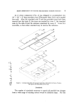
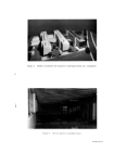
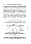
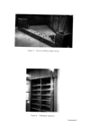
44 JOURNAL OF THE SOCIETY OF COSMETIC CHEMISTS where this might occur we decided to install balanced draught fume cup- boards in which 80% of the extracted air is provided from a source external to the laboratory with only 20% being extracted from the laboratory itself. With laboratories where air conditioning was required, we decided to group these together at one end of the building so that they could be served from a common non-recirculatory plenum system. In this area, extraction is effected either through fume cupboards or grilles in laboratories where there are no fume hoods. The mechanical services The services demanded by the laboratory function were pressurized cold water, hot water, town gas, central vacuum and compressed air, steam at 15 psi, electricity and also a separate primary earth. Consideration was also given to the provision of a piped nitrogen gas supply, but a study of the pattern of the laboratory usage of this gas led us to the conclusion that the capital cost of such an installation could not be justified in our own case. We also investigated the feasibility of a piped distribution system for distilled water but decided that the use of local units was to be preferred on the grounds of economy of usage of distilled water and the cost of installing the pipework, together with the additional maintenance costs occasioned by it. Design work for the mechanical services installation has been provided by external consultants who recommended the following system. Each service would have a vertical main rising from the basement plant room and this main would then serve a horizontal sub-main on each floor, which in turn would provide a supply for the lateral branches serving the individ- ual laboratories on a modular basis. At this time we also considered the type of pipework to be used for the effluent from the laboratories. Although previously we had used short runs of chemical lead wastes quite satisfactorily in the old laboratories, we now had to consider methods of supporting the 50 foot lengths of down-pipe, with the attendant costs both in terms of space and money. We therefore turned our attention to glass pipelines and were pleased to find that the manufacturers had just introduced a new type of joint to replace the older butt ioint which, in our opinion, had been the weakness of any glass drain- age installation. By specifying the relatively rigid glass pipelines, we were able to install the whole effluent system with considerable economies in the space required.
Purchased for the exclusive use of nofirst nolast (unknown)
From: SCC Media Library & Resource Center (library.scconline.org)