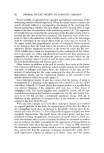
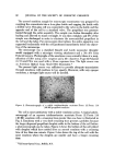
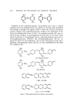
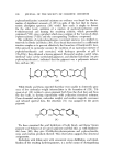
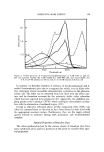
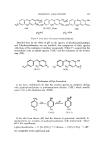
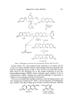
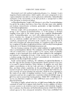
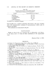
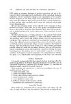
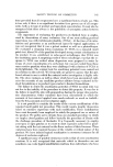
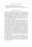
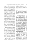
AEROSOL EMULSIONS AND FOAMS 91 Foam Density Foam density was obtained by weighing 350 cc of the foam within one minute after discharge. Wetting Wetting was determined by discharging the foam onto a paper towel and noting the time until visual wetting of the paper was observed. Microscopic Apparatus The apparatus for microscopic examination of aerosol emulsions was con- structed as follows: a 4-oz glass bottle was capped with a standard Precision valve with an 0.08-in. i.d. tail piece. A hole, 0.08 in. in diameter, thus corre- sponding to the diameter of the tail piece, was drilled through the entire valve to the dip tube. This essentially converted the valve into an extension of the dip tube. A glass pressm'e cell was prepared by placing an oval brass shim, I rail thick, between two pieces of ordinary glass and fusing the edges of the glass together, leaving the brass shim sandwiched between the sheets of glass. The brass shim inside the cell was removed by immersion in nitric acid, leaving a cell with a uniform, inside depth of I rail. The ends of the oval cell were fused to short lengths of 0.08-in. i.d. glass tubing. The outside dimensions of the cell were 2 mm thick, 5 mm wide, and 7 mm long. One end of the cell was connected to the stem of the valve on the bottle and the other end to the tail piece of a standard Precision valve with a 0.018-in. inlet orifice and foam actuator. The apparatus is illustrated in Fig. 1. The oval cell is located midway between the top valve and the valve on the glass bottle. Figure 1. Apparatus for microscopic observation of aerosol emulsions

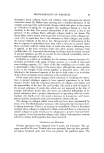
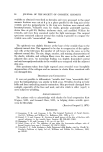
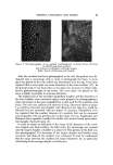
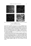
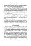
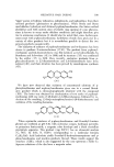
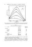
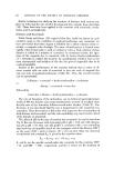
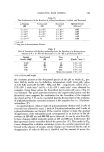
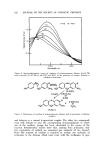
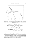
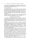
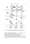
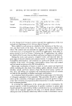
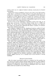
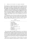
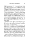
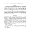
92 JOURNAL OF THE SOCIETY OF COSMETIC CHEMISTS The aerosol emulsion sample for microscopic examination xvas prepared by weighing the concentrate into a 4-oz glass bottle and capping the bottle with a drilled valve. The glass cell was connected to the valve on the bottle and the opposite end of the cell to a standard valve. The propellant was pressure loaded through the entire assembly. The sample was shaken thoroughly after loading and allowed to stand overnight. It xvas then reshaken and 5'% of the sample was discharged in order to eliminate the nonemulsified propellant in the cell and dip tubes. For microscopic observations, the entire apparatus xvas supported horizontally with the cell positioned immediately below the object- rive of the microscope. The microscope xvas a standard Bausch and Lomb monocular dynoptie model equipped with a microipso viewing attachment and a 31/4 x 41/4 Leitz Polaroid camera. Photographs of the emulsions were normally taken at a mag- nification of 150x using a 15x eyepiece and a 10x objective. Type 52 Polaroid 4 x 5 Land Film was used with a 15-see exposure time. The light source was an American Optical Corp. Model 651 illuminator.* The present light source was sufficient to provide adequate transmission through emulsions with medium to low opacity. However, with very opaque emulsions, a stronger light source will be needed. Figure 2. Photomicrograph of a stable triethanolamine myristate/Freon 12/Freon 114 (40/60) propellant emulsion The cell is most satisfactory with a stable enmlsion system. A typical photo- micrograph of an aqueous h'iethanolamine myristate/Freon loe/Freon 114 (40/60) emulsion with a creaming tinhe greater than one hour is illustrated in Fig. oe. Emulsions with a very short creaming time present a problem because the larger dispersed propellant droplets settle to the bottom of the cell before a photomicrograph can be taken. Figure 3 shows the bottom of the cell plated with droplets which have settled from an aerosol enmlsion with a creaming time of less than one minute. Figure 3 also shows the top of the cell xvith the sanhe emulsion where the droplets are smaller and have a longer creaming time. *American Optical Corp., Buffalo, N.Y.
Purchased for the exclusive use of nofirst nolast (unknown)
From: SCC Media Library & Resource Center (library.scconline.org)