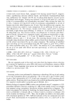
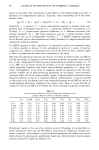
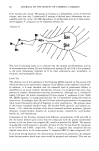
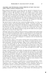
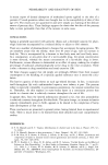
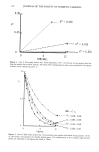
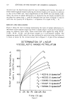
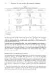
VISCOELASTIC PARAMETER MEASUREMENTS 119 such plugs of equal dimensions were drawn before every run and an electronic ther- mometer probe 6 was inserted for monitoring the temperature of the material during the experiment. The pressing rate of the material placed between two horizontal circular plexiglass plates under a known stress was magnified with the help of a LVDT unit mounted on the top plate and was chart-recorded directly. Sample plugs were loaded onto the bottom plate, which was permanently affixed on a tripod. The top plate, with a guide rod attached underneath it, moved freely vertically through the central hole of the bottom plate (Figure 1). Additional plexiglass plates could be APPARATUS 0.9 v.o I ,• ½ 12.5 I ---• i. 2 (...- ( 18.8 12.$ -4 3.8• •- 0.236 0,•5 • 18.7 '' 9.8 Platform Top Plate Teflon Plucj Bottom Plate Metallic Rod Guide Plate Tripod Stand All dimensions are In cm. Figure 1. 6 Electronic Digital Thermometer, Fisher Scientific Co.

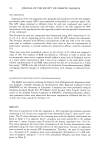
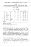
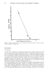
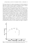
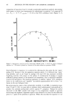
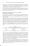
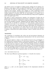
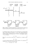
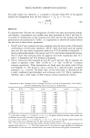
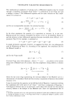
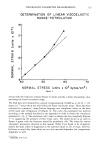
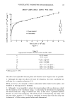
120 JOURNAL OF THE SOCIETY OF COSMETIC CHEMISTS mounted over the fixed bottom plate for ease in handling and cleaning. Any level of stress could be applied simply by placing the desired weight on the top plate in addition to that of the LVDT unit. Since magnification of the LVDT unit was already estab- lished, the extent of sample deformation, h, represented by the height traveled by the top plate for a given time, t, could be obtained from the chart recordings. It may be noted that the quantity H in Equation 1 or Equation 10 is equal to (H 0 - h). RESULTS AND DISCUSSIONS Figure 2 shows the chart recordings representing the extent of sample deformation, h, (see above) of five separate single runs (with 3 sample plugs in each run) for petrolatum using five different stress levels. These stress levels were applied by using 48.44-, 53.88-, 58.44-, 63.88-, and 68.44-gm weights on 1.2-cm-diameter samples. The engineering strain (h/H0) after 65 sec was calculated for each stress using the respective h values as shown by the vertical dotted line in Figure 2. A plot of the calculated DETERMINATION OF LINEAR VISCOELASTIC RANGE-PETROLATUM IOO 80 60 40 20 F5 F$ F2 fi 2 f I = 42016.6 dynes/cm 2 F 2 = 46:553.6 dynes/crn 2 F.• = 50690.5 dynes/cm 2 F 4 = 55027.5 dynes/cm F 5 = 59 564.5 dynes/cm 2 0 25 50 75 I00 125 150 Time (t) sec Figure 2.
Purchased for the exclusive use of nofirst nolast (unknown)
From: SCC Media Library & Resource Center (library.scconline.org)