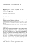
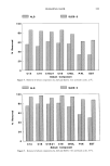
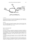
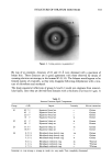
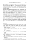
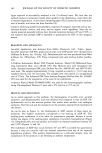
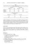
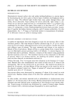
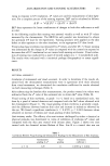
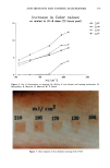
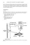
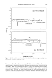
380 JOURNAL OF THE SOCIETY OF COSMETIC CHEMISTS least on a relative basis. Both techniques involve scanning along the length of a fiber, the level of resolution depending on the rate of scanning. Using a combination of these two methods, we have studied the deposition, substantivity, and buildup of formula- tions containing either a cationic polymer or a keratin hydrolysate in conjunction with an anionic ethersulfate surfactant. EXPERIMENTAL MATERIALS The European dark brown hair fibers used in these studies were rinsed extensively in demineralized water prior to treatment. The following formulations were prepared: 1) Cationic cellulose ether (CCE): 2% (0.5%) Sodium laureth sulfate: 14% (14%) Demineralized H20: 84% (85.5%) pH 6.3 2) Keratin hydrolysate (Ker): 5% Sodium laureth sutfate: 14% Demineralized H20: 81% pH 6.4 ELECTROBALANCE COMPUTER O/ RECORDER - o.+ MELM• BER I Figure 1. Experimental arrangement for the measurement of fiber wettability by the liquid membrane method (1).

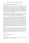
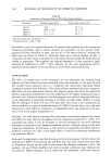
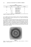
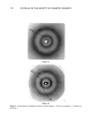
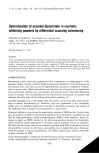
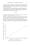
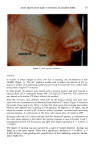
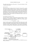
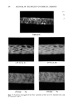
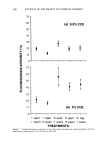
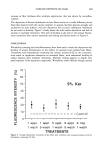
SURFACE DEPOSITS ON HAIR 381 The sodium laureth sulfate has an EO number of 2. The keratin hydrolysate is CTFA "hydrolyzed animal keratin." FIBER TREATMENT Fibers were mounted on stainless steel tabs and treated for 5 min at 30øC in a gently stirred solution. They were rinsed five times, 1 min each, with 200 ml demineralized water. After conditioning the fibers overnight at 65% RH and 2 IøC, a small segment of each fiber was removed for determining a receding contact angle O• by immersion wettability (6), and the rest of the fiber was scanned using the liquid membrane wetta- bility method (1). To assess the buildup of deposits on the fiber surface, the treatment was repeated three times the two levels of treatment are indicated by 1 x and 4 x in the figures and tables. Fiber perimeters were calculated from major and minor axes determined by microscopy. LIQUID MEMBRANE WETTABILITY SCANNING Our liquid membrane wettability scanning procedure has been discussed in a previous publication (1). The experimental arrangement is diagrammed in Figure 1. As the liquid membrane moves up the fiber, forces are generated at the two liquid surfaces, advancing and receding the net force is given by F = P'yLv(COS 0 a -- COS 0•), where P is the fiber perimeter, 'Yrv the surface tension of the membrane liquid, and and O• the contact angles in the advancing and receding modes. Assuming that cos determined in the separate immersion experiment, does not vary along the fiber permits calculation of cos 0•, a measure of surface energy. In these studies we used demineral- ized water as the membrane liquid. Although the assumption that equilibrium wetting PHOTOMULTIPLIER I X-Y RECORDER FILTER{360-IOOnm} . ¾ j COMPUTER ] Figure 2. Diagram of the Leitz MPV 1.1 microspectrophotometer with the PLOEMOPAK attachment for fluorescence measurements.
Purchased for the exclusive use of nofirst nolast (unknown)
From: SCC Media Library & Resource Center (library.scconline.org)