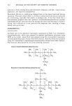
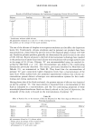
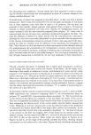
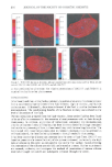
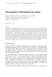
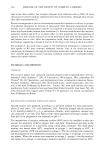
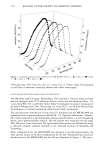
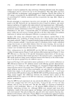
272 JOURNAL OF THE SOCIETY OF COSMETIC CHEMISTS Numerous works have demonstrated anatomical differences in cutaneous perfusion, skin thickness, viscoelastic properties, skin microtopography, and skin condition (2-7). Thus, it is not surprising that various investigators have shown variability in minimal erythemal dose (MED) as a function of anatomical site (8-10). Possible explanations for these regional MED differences include variations in blood flow, epidermal thickness, melanin content and melanosome characteristics (11), surrounding constitutional skin color (12), and visual perception (13). However, while these variations may explain natural photoprotection differences, their effects on sunscreen film formation and, there- fore, sunscreen efficiency are not known. Consequently, accurate assessment of SPF efficiency of sunscreen products intended for sites other than the back would be greatly facilitated by sunscreen testing on the site of intended use. FDA-proposed sunscreen testing guidelines mandate irradiation of test subsites no smaller than 1 square centimeter (1). This minimum size restriction makes sunscreen testing impractical on anatomical sites, such as the face, that cannot support the required number of test subsites. Furthermore, current ultraviolet light (UV) delivery systems (solar UV simulators) are the evolutionary products of designs engineered to conform to the requirements of the FDA therefore, most if not all of these systems do not account for subject discomfort or facilitate subject consent to SPF testing anywhere else on the body. Thus, practical SPF testing on anatomical sites other than the back requires the design of an instrument that can address the technical and logistical concerns associated with such testing. The development, design considerations, and use of an instrument engineered for fa- cilitating SPF testing anywhere on the body are discussed. Comparison of SPF results produced using the instrument, named MICRO-SPF, and results produced using a stand-alone solar UV simulator (SSS) are presented. Additionally, the effect of anatom- ical site on SPF efficiency is examined. MATERIALS AND METHODS M1CRO-SPF INSTRUMENT The MICRO-SPF instrument delivered UV energy from a solar UV simulator to an intended irradiation site. The principle of operation of the MICRO-SPF was based on the ability of multiple silica-core optical fibers to deliver UV profiles and fluence levels comparable to those delivered by SSSs. The primary components of the MICRO-SPF consisted of a 5-furcared optical fiber bundle, electromechanical shutter housing, five delivery optical fiber bundles, a mounting disk, and a personal computer (Figure 1). The MICRO-SPF was optically interfaced to the output of an SSS (Solar UV Simulator A). Using an F2 focusing lens, filtered UV energy was focused into the common end of a 5-furcared optical fiber bundle (C Technologies, Verona, N J). The common end of the 5-furcared optical fiber contained 60 silica-core microfibers (0.2-mm core diameter C Technologies) arranged to create a 2.1-mm aperture. Each leg of the 5-furcared optical fiber bundle contained 12 microfibers that transmitted UV to a housing (Fibertronics, CA) containing five electromechanical shutters (Vincent Associates, Rochester, NY). Similar UV spectral distributions (Figure 2) were achieved in each leg of the 5-furcared optical fiber bundle through randomized arrangement of the

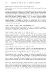
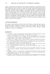
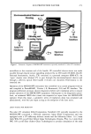
SUN PROTECTION FACTOR 273 Electromechanical Shutters and Housing • .... ': Filtering and ß . ...... Focusing Optics • Driv• Solar UV Program Simulator Operator Interface To Skin Interface Figure 1. Schematic diagram of MICRO-SPF instrument optically interfaced to solar UV simulator. microfibers at the common end of the bundle. PC-controlled shutter status was made possible through digital output signalling produced by an I/O board (AT-MIO-16L-09 National Instruments, Austin, TX) contained in a personal computer (IBM-AT). An "open" shutter state allowed UV to pass through the electromechanical shutter and through a delivery optical fiber bundle (1.0-mm core diameter Fibertronics) to the intended site. Operation of the MICRO-SPF instrument was controlled via a custom program (written and compiled in PowerBASIC, Version 3.0 Brentwood, CA) and PC interface. The program performed necessary shutter diagnostics before each irradiation series to ensure proper operanon of the MICRO-SPF equipment. Subsequent to the diagnostics proce- dure, an estimated MED dose (time) was requested as input from the MICRO-SPF operator. From this input, a geometric series of irradiation doses was calculated and administered, with the user input acting as the midpoint of the dose series. LIGHT SOURCE FOR MICRO-SPF The solar UV simulator (Oriel Corporation, Stamford, CT) optically mounted to the MICRO-SPF contained a 450-watt xenon-arc lamp (Oriel Corporation) and was equipped with a UV-reflecting dichroic mirror and the following filters: 1) a 3-mm thick WG 295 cut-off filter (Schott Glass Technologies, Duryea, PA) 2) a 2-mm thick WG 305 cut-off filter (Schott Glass Technologies) to produce simulation of the solar
Purchased for the exclusive use of nofirst nolast (unknown)
From: SCC Media Library & Resource Center (library.scconline.org)