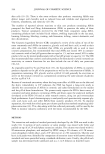
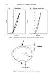
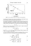
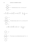
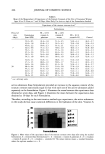
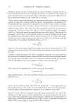
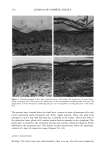
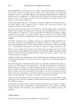
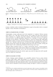
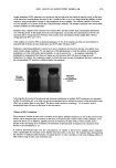
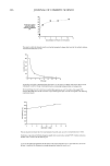
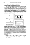
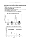
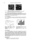
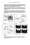
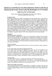
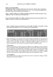
252 JOURNAL OF COSMETIC SCIENCE (a) Untreated hair (b) Polymer treated hair 160 140 10 120 40 •'0 -1 -0.5 0.5 I 1.5 2 -1 -0.5 0 0.5 I 1.5 Distance (rnrn) Distance (rnrn) Figure 2. Plots of force vs deformation for untreated and polymer-modified hair loops. P Figure 3. Deformation of a thin ring with a circular cross section. Delta y

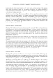
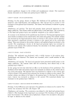
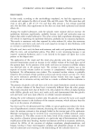
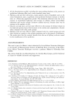
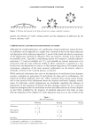
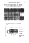
DYNAMIC HAIRSPRAY ANALYSIS 2 5 3 2.2 2 1.8 1.6 1.4 1.2 1 0.8 0.6 1.1 1.2 1.3 1.4 1.5 1.6 1.7 log(R) -m (Linear Fit) Figure 4. Force as a function of diameter for steel rings at a constant deformation. were obtained for rudimentary loops obtained by imparting the circular shape to a wire and then linking its ends by twisting them around each other. Let's consider the deformation of multiple fiber assemblies and how they can be ap- proximated by using equation 1. For example, in order to evaluate the deformation of tresses of fibers characterized by different fiber thickness and the same total volume, the number of fibers in each bundle has to be calculated from the following relationships: V• = V 2 (3) Bundles 1 and 2 are characterized by the same fiber volume (or weight, assuming the same density of fibers in both bundles). nlTrrl 2 1 = n2Trr2 2 I (4) n 2 = n t (r,/r2) 2 (5) where V1, V2, rt, r2, n•, n 2 are volumes, radii, and numbers of fibers in bundles 1 and 2, and 1, is the length of a fiber bundle. A circular (or omega-loop) configuration is applied to both bundles of fibers. At a given deformation, By, the forces in each bundle are given by the following equations: •11•yEI •11•yE 4 P1 = -- (6) 4 4 = = (7) 4 ß rr l
Purchased for the exclusive use of nofirst nolast (unknown)
From: SCC Media Library & Resource Center (library.scconline.org)