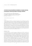
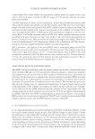
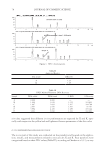
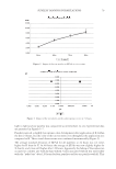
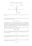
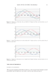
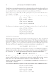
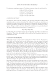
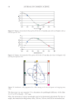
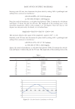
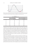
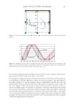
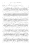
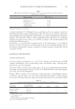
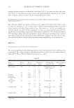
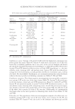
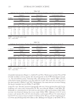
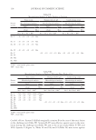
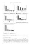
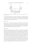
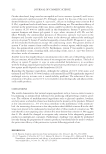
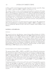
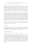
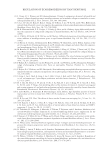
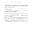
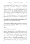
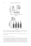
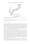
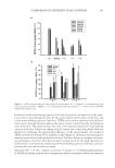
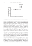
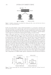
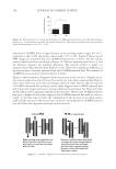
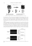
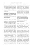
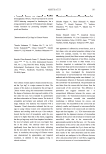
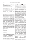
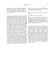
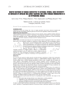
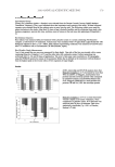
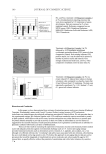
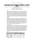
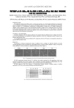
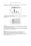
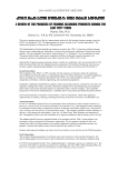
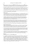
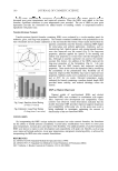
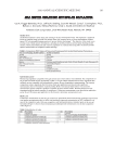
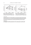
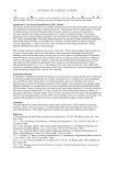
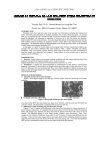
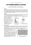
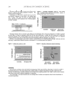
JOURNAL OF COSMETIC SCIENCE 100 maximum magnitude, which in this example is at 60 degrees. Since the value at 60 de- grees was not previously calculated, it is calculated here: Amplitude Sin(60) Sin(60 1015) 1.69 = + − = The intensity, which is the square of the amplitude, equals (1.69)2= 2.86. With 650 nm, determine the phase shift by taking 2π/λ × pathlength and adding π for constructive interference: ( / / .4663 2 650 1275) 360 2 15 π π π × × + = = 15.4663 radians or, 886 degrees Finally, the result of interference is calculated and plotted. Table III contains the calcula- tion and Figure 25 shows the plot for 650 nm. The amplitude of the resulting wave is the maximum magnitude, which in this example is at 180 degrees. Since the value at 180 degrees was previously calculated, it is read from Table III. The intensity, which is the square of the amplitude, equals (0.242)2 = 0.06. The intensities for the three primary colors are plotted to determine the total color of the interference fi lm. In addition, one can add the respective intensities for the wavelengths that correspond to constructive and destructive interference. These wavelengths were determined in the example in the section on refl ective interference. The constructive Table II Calcuation for 550 nm x y = sin(x) y = sin(x-1015) Sum 0 0 0.906308 0.906308 45 0.7071 0.939693 1.646799 90 1 0.422618 1.422618 135 0.7071 −0.34202 0.365087 180 0 −0.90631 −0.90631 225 −0.7071 −0.93969 −1.6468 270 −1 −0.42262 −1.42262 315 −0.7071 0.34202 −0.36509 360 0 0.906308 0.906308 Figure 24. Calculated result of interference at 550 nm.

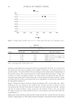
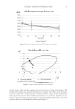
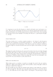
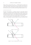
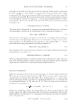
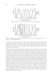
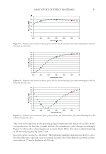
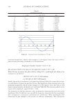
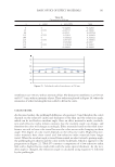
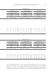
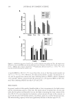
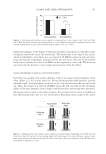
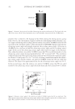
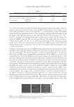
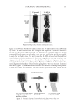
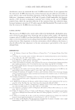
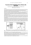
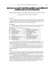
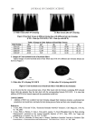
BASIC OPTICS OF EFFECT MATERIALS 101 interference is at 510 nm, with an intensity of four. The destructive interference is at 425 nm and 637.5 nm, with an intensity of zero. These values are plotted in Figure 26, where the intensities of other wavelengths were added to fi ll in the curve. COLOR TRAVEL As discussed earlier, the pathlength difference of equation 13 (and therefore the color) depends on the refractive index and thickness of the fi lm and the refraction angle, which can be tied back to incident angle. Once an effect material is made, its thick- ness and refractive index remain constant, but the incident angle can change, and therefore the color will change accordingly. Effect materials based on thin-fi lm inter- ference are said to have color travel because the color moves with changing incident angle. The degree of color travel depends on the refractive index. High-refractive- index materials have short travel and low-refractive-index materials have longer travel. When the incident angle is varied from normal incident toward a grazing angle, the pathlength gets shorter and the color travels backwards, which is opposite to the progression in Figure 22. Table IV contains a comparison of a low-refractive-index fi lm with a high-refractive-index fi lm with the same optical thickness. As the inci- dent angle is changed, the refraction angle is calculated using equation 4, followed by the pathlength. Figure 25. Calculated result of interference at 650 nm. Table III Calcuation for 650 nm x y = sin(x) y = sin(x-886) Sum 0 0 −0.24192 −0.24192 45 0.7071 −0.85717 −0.15006 90 1 −0.9703 0.029704 135 0.7071 −0.51504 0.192069 180 0 0.241922 0.241922 225 −0.7071 0.857167 0.150061 270 −1 0.970296 -0.0297 315 −0.7071 0.515038 -0.19207 360 0 −0.24192 -0.24192
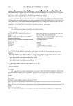
Purchased for the exclusive use of nofirst nolast (unknown)
From: SCC Media Library & Resource Center (library.scconline.org)