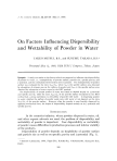
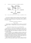
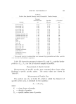
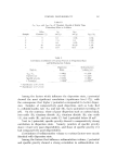
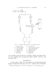
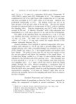
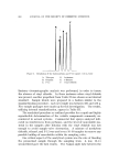
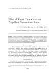
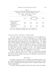
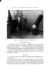
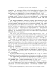
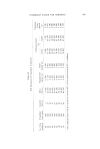
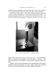
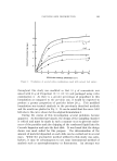
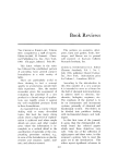
GAS CHROMATOGRAPHV OF AEROSOLS 355 t ¾,•ure 1. Schematic representation of the analytical systems A. Helium supply H. Piercing valve B. Pressure regulator I. Point of entry into aerosol C. Flow controllers J. Vapor-liquid interface D. Injection block K. Halloomid columns E. Sampling valve L. Detector block F. Sight tube M. Outlet ports G. Bleed valve N. Sample can valve resulted in improvements in resolution, tailing, and elution time. The new sampling valve incorporated sliding Teflon •* interfaces and no rubber seals. ]•XPERIMENTAL A Perkin-Elmer Model 820 dual-column gas chromatograph with thermal conductivity detection was used. Columns were of stainless * Registered trademark of E. I. du Pont de Nemours & Co., Inc., Wihnington, Del.

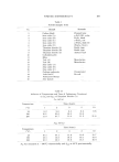
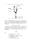
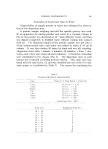
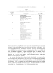
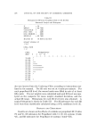
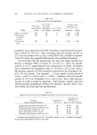
356 jOURNAL OF THE SOCIETY OF COSMETIC CHEMISTS steel (9.2 m X 3.2 mm o.d.) containing 60-80 mesh Chromosorb W (AW-DMCS) coated with 20% Halleomid M-18. The columns were conditioned at 100 øC for eight hours with a helium flow of 5-10 ml/min, and then overnight at 85 øC with a flow of $0 ml/min. Analysis was performed isothermally at 70 øC. The helium carrier gas was at an inlet pressure of 80 psi and a flow of 60 ml/min. The gas was passed through the injection block at a temperature of 280 øC, prior to entering the sampling valve. Detector temperature was 262 øC with a filament current of 200 mA. A Moseley Recorder* with a disc integrator was maintained at 0-1 mV and a speed of 0.5 in./min for the investigation. The outlet of the injection block was attached to a 5 em X 3.2 mm o.d. stainless steel tube, and then to a reducing union and a 7.6 em X 1.6 mm o.d. tube. The latter was connected to the 2-•1 sampling valve. • A 7.6 em X 1.6 mm tube carried the sample directly to the column (schematic diagram, Fig. 1). Aerosol containers were sampled at ambient temperature after pres- surizing with nitrogen to 110-20 psi with a pressure-filling buret. A sample-piercing valve with a threaded fitting{ was attached to the side of the sample can, using a No. 1 steel tapped gasket and stainless steel hose damps. The point of entry into the can was low enough so that the can was pierced well below the boundary of the liquid phase. A 6.4-ram flare fitting, welded to a 3.2 mm-l.6 mm reducing union, was attached to the threaded end of the pieming valve. This assembly was in turn attached to a 7.6 em X 1.6 mm stainless steel tube from the 2-•1 sampling valve. A $ ø taper valveõ was used to bleed the liquid sample through the valve, thereby permitting a continuous loop of liquid through the valve. Samples were bled slowly for 10 seconds and then the bleed valve was quickly dosed to avoid fraetionation and insure representative sampling. A 6.4-mm o.d. Nalgon©l! sight tube was in- serted in the assembly between the sampling and bleed valves to observe the flow of liquid. Standard ]reparation and Calibration Standard blends of propellants as listed in Table I were prepared by adding the components as liquids to aerosol containers. In the in- * Model 7127 A, Moseley Division, Hewlett-Packard Corp., San Diego, Calif. t Model No. 2015, Carle Instrument Co., Fullerton, Calif. { Model No. 5847, Builders Products, New York, N.Y. õ Hoke Rubber Co., Hartford, Conn. II Registered trademark of Nalge Co., Rochester, N. ¾.
Purchased for the exclusive use of nofirst nolast (unknown)
From: SCC Media Library & Resource Center (library.scconline.org)