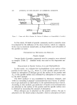
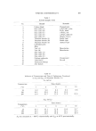
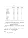
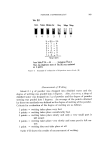
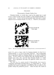
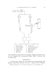
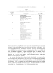
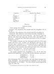
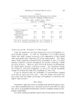
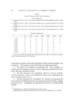
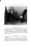
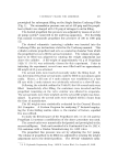
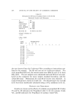
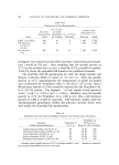
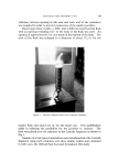
390 JOURNAL OF THE SOCIETY OF COSMETIC CHEMISTS Procedure The following formulation, with weights given in grams, was studied' PVP/VA E535' 80 Myristyl alcohol 2 Lantrol* 2 Isopropyl myristate 2 SDA//40 anhyd. 914 To pressurize: Concentrate 30 Propellant 12/11 (50:50) 70 Approximately 100 g of finished product was placed into 2-oz aerosol cans using the cold process of filling. Valves with different sized stem and body orifices were attached to each container. Five such combina- tions were studied. Actuators with an opening of 0.016 and 0.018 inch were also used. Table III illustrates the various combinations studied. Table III Valve Combinations for Aerosol Hair Sprays Code Stem Orifice, Body Orifice, No. In. In. Actuator 1 0.01.3 0.080 0. 016 MB-RT .3 0.018 0.080 0.016 MB-ST 4 2 X 0. 020 a 0. 080 0. 020 MB-ST 8 0.01.3 0. 018 0. 018 6 0.01.3 0. 018 0. 016 b 7 0.01.3 0.018 0.016 c Extended taper end. 4-Channel mechanical breakup type. 2-Channel mechanical breakup type. The particle size distribution for each of the above preparations was determined using the Cascade Impactor Model CI-S-6. This instru- ment was designed for use in a vertical position and to have a flow rate of 12.5 1./minute. After assembling the instrument with the glass slides in place, the vacuum was adjusted to 17 in. of Hg. Approximately 5 to 6 g of sample was slowly introduced into the sampling chamber and the particles were allowed to collect upon the slides. The vacuum was then slowly released and the glass slides were removed. Room tempera- ture and sample temperature was maintained between 23-25 øC. * PVP/VA E535, General Aniline and Film Corporation, N.Y. Lantrol, Maimstrom Chem- ical Corp., Linden, N.J.

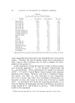
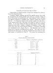
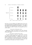
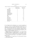
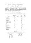
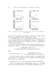
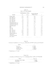
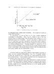
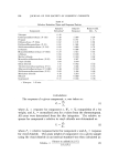
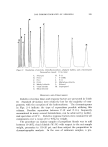
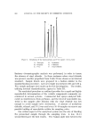
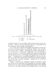
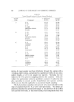
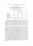
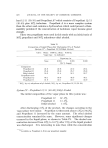
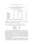
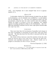
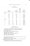
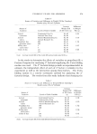
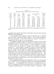
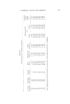
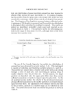
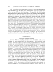
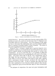
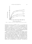
PARTICLE SIZE DISTRIBUTION 391 The weight of sample was determined by weighing the can of hair spray before and after removal of the sample. The amount of material deposited within the sampling chamber and on each of the slides was determined by weighing the chamber and the slides before and after the collection of the particles. The difference in weight was calculated and represents the amount of material in each of the particle size ranges. From these results, the cumulative weight per cent of particles in each of the ranges was calculated. The results are shown in Table IV and Figs. 2 and 3. These are the average results of three determinations made upon each sample. Table IV Particle Size of Hair Sprays Fitted with Selected Valve Combinations Valve Combination Number Microns 1 2 4 8 16 32 Cumulative Weight Per Cent 1 0.44 1.06 2.24 3.65 3.87 4.35 3 0.14 0.65 1.85 2.24 3.53 4.35 AA3" 0.35 1.50 2.35 4.70 5.80 6.25 4 0.50 1.52 2.40 3.75 3.99 4.46 5 0.49 1.80 3.45 6.80 7.43 8.35 6 0.44 1.55 4.02 7.10 7.50 9.22 7 0.57 2.10 4.90 8.96 9.82 10.68 "This sample contains 85% Propellant 12/11 (50:50) as compared to 70% Propellant 12/11 (50' 50) used for the other samples. The per cent solids was the same for all samples. DISCUSSION OF RESULTS Since this study was concerned primarily with determining the relative proportion of small sized particles to larger ones, the Cascade Impactor, with an upper limit of 32 u, can be used. Figure 2 shows a typical plot of particle diameter versus cumulative weight per cent. Particle size distribution data, in many instances, follows a logarithmic probability relationship and when the data are plotted on logarithmic probability paper, a straight line relationship should result. However, it can be noted from Fig. 2 that a straight line is obtained from about 1 to 8 • followed by a bending of the curve from 8 to 32 •. This deviation can be explained on the basis of the limitation of the Cascade Impactor for classifying particles much above the 16-u size. This is especially true where a large number of particles are present having a diameter
Purchased for the exclusive use of nofirst nolast (unknown)
From: SCC Media Library & Resource Center (library.scconline.org)