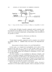
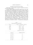
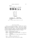
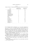
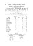
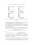
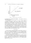
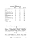
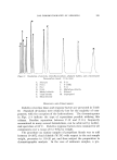
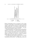
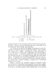
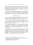
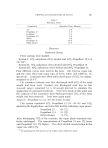
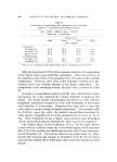
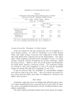
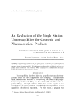
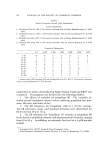
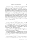
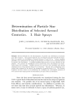
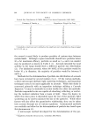
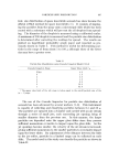
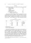
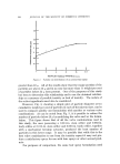
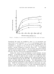
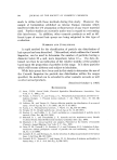
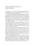
392 JOURNAL OF THE SOCIETY OF COSMETIC CHEMISTS 5O 2O • 5 0.5 0.1 I I I I 4 8 16 32 EQUIVALENT PARTICLE DIAMETER, micro ns Figure 2. Particle size distribution of an aerosol hair spray greater than 32 •. All of the results show that the major portion of the particles are above 32 • and in no case has more than 11 weight per cent of particles below 32 • been present. One of the purposes of this study has been to determine this relationship and to use the obtained relation- ship as a measure of possible toxicity or lack of toxicity. The nature of the active ingredients must also be considered. However, Fig. 3, showing a simple plot of particle diameter versus cumulative weight per cent of particles in each of the micron sizes, can be used to compare quickly one formulation with another or various valve combinations. As can be noted from Fig. 3, it is possible to reduce the number of particles below 20 • by modifying the valve and/or the formu- lation. This figure shows that of all the valve combinations used in this study, the ones possessing a 0.013-in. stem orifice and 0.080-in. body orifice or 0.018-in. stem orifice and 0.080-in. body orifice, together with a mechanical breakup actuator, produced the least number of particles in this lower range. It may be possible that while this is the best valve combination to use from the toxicity aspect it may not pro- duce a satisfactory spray for use with hair sprays or other aerosol prod- ucts. For purposes of comparison, the same hair spray formulation used

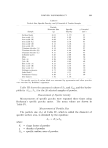
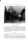
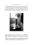
PARTICLE SIZE DISTRIBUTION 393 P'/,•ttre ,?. EQUIVALENT PARTICLE DIAM ETER,m i cro ns Evaluation ()f several valve combinations used with aerosol hair sprays throughout this study was modified so that 13 g of concentrate was mixed with 83 g of Propellant 12,/11 (30:30) and packaged using valve combination 3. As there is a greater percentage of propellant in this formulation as compared to the previous one, it would be expected to produce a greater proportion of particles below 20 u. This modified formulation was treated similarly to the previously described methods and the results are plotted in Fig. 3. It can be noted that the curve AA3 falls above the curve shown for the original formulation 3. During the course of this investigation several problems became apparent. As described previously, the design of the sampling chamber is critical and must be made in such a manner so as to prevent coales- cence of the particles and also dripping of the condensed liquid into the Cascade Impactor and onto the first slide. It was found that the design shown was most suited for this purpose. The determination of the amount of material deposited on each slide can be carried out in several ways. While the gravimetric method utilized in this study was satis- factory, it may be advantageous to use some instrumental method of analysis such as spectrophotometry or fluorometry. An attempt was
Purchased for the exclusive use of nofirst nolast (unknown)
From: SCC Media Library & Resource Center (library.scconline.org)