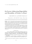
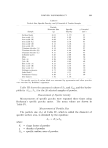
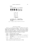
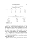
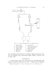
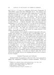
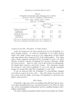
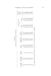
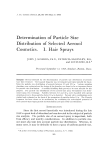
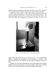
376 JOURNAL OF THE SOCIETY OF COSMETIC CHEMISTS •. 'i' ':' •.' -•a• •." .:: •'.:'•i ..... ¾•.•. -:. 5':. 5 .: . r,• .. ß . . • . .. .• •?' •..} .• •:.:. •.•.• . ..• -.. -• • .• . -.. .•½.• . .,..•- :.-• Figure 1. Kartridg Pak Single Station Undercap Filler Experimental Design To study the effects of variables on propellant fill, a total of 640 aerosol units were filled on the Undercap Filler in a statistically deter- mined random manner (1). The aerosol container/valve designation and the experimental schedule are shown in Tables I and II, respectively. To study the fill tolerances for the Propellant 142b/11 (•0 :,50) and the Propellant 12 system, approximately fifty aerosol units were filled at each fill level studied. Procedure To study the effects of variables on propellant fill the following proce- dure was used: The four aerosol container/valve combinations were numerically des- ignated and were preweighed on the Sauter-Toppan Balance estimating to the nearest 50 rag. The numbers assigned represented the sequence in which the aerosol units were filled. A total of 640 aerosol units were

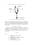
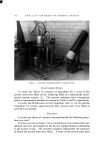
UNDERCAP FILLER FOR AEROSOLS 377 preweighed for subsequent filling on the Single Station Undercap Filler (Fig. 1). The accumulator pressure was set at 450 psig and the propel- lant cylinder was charged with 120 psig of nitrogen to aid in filling. The desired propellant line pressure was adjusted by means of an S-C air pump system* connected to the undercap apparatus. The Kartridg Pak manual recommends propellant line pressures of 500 to 1000 psig (2). The desired volumetric (metering) cylinder was inserted into the Undercap Filler per instructions stated in the Undercap manual. This cylinder contains propellant and acts as a metering chamber from which the propellant leaves to fill the aerosol container. The volume of propel- lant to be filled was adjusted by rotating the weight adjustment nut above the cylinder. A fill weight of approximately 62 g of Propellant 142b/11 (30:30) was arbitrarily chosen for this experiment. Prior to initiating the experiment, several cans were filled until an approximate fill weight of 62 g was attained. The aerosol units were inserted manually under the filling head. It was determined that four aerosol units could be filled in one minute quite easily. Hence, a fill rate of 4 units/minute was established as a fast fill rate while 2 units/minute was arbitrarily selected as a slow fill rate. Following the schedule outlined in Table II, the 640 aerosol units were filled. Immediately after filling, the containers were inverted and the propellant remaining on the valve exterior was allowed to evaporate. The aerosol units were then weighed and the actual fill weight was deter- mined. In general, the aerosol units were weighed within 5 hours from the time of manufacture. The fill weights were statistically evaluated by the General Electric 265 Computer. A Fortran Program for analyzing 2 n factorial employ- ing the Yates folding routine where n, the number of factors, equalled five was utilized. To study the fill tolerances of the Propellant 142b/11 (30: 50) and the Propellant 12 systems a modification of the above procedure was used. The aerosol units were numerically designated and preweighed to the nearest milligram. Each unit consisted of a Continental Can Co. 202 X 214 container with a Risdon Manufacturing Co. 6422 valve. The propellant line pressure was set by adjusting the S-C pump. The volume of propellant to be filled was adjusted by rotating the weight adjustment nut to the desired position. The 100-em a volumetric cylin- * S.C. Hydraulic Engineering Corp., 14032 S. Avalon Blvd., Los Angeles 61, Calif.
Purchased for the exclusive use of nofirst nolast (unknown)
From: SCC Media Library & Resource Center (library.scconline.org)