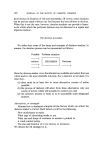
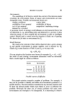
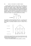
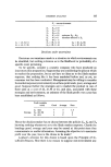
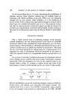
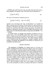
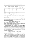
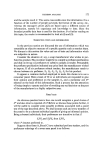
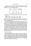
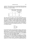
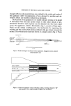
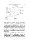
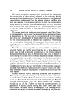
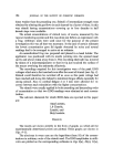
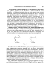
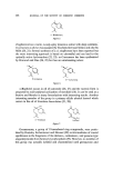
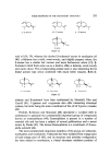
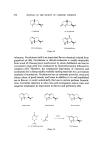
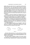
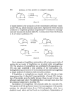
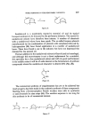
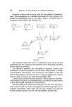
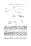
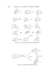
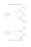
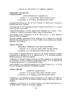
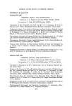
RESPONSE OF THE FROG OLFACTORY SYSTEM 187 changes in flows and concentrations are confined to the switch and nozzle of the applicator itself'. Contamination of' one odorant by another and ad- sorption effects are therefore reduced to a minimum. The function of' the applicator is to enable odorant streams to be added to and mixed with the main carrier stream so that odour stimuli of' pre- &term[ned duration and sequence can be directed into the f'rog's nasal cavity. The applicator, which is illustrated in Fig. 3, consists of three parts. These are the stream switching part, the mechanism for operating the switches and the nozzle which mixes and directs the gas stream towards the animal. The switches and nozzle are shown on a larger scale in Fig. 4. There Compressed Odour stream I •% (I,Sml/min) •_ •_• Carrier • • (100 •/min) .... • (I.Sml/m[n) • Suction • •'- Carrier (50mt/m[n) • channel 4 Suct (lO0 ml/min) ! I IO cm Figure 3. Scale drawing of six-channel odour applicator. (Saggital section, channel 1 off, channel 4 on.) Odour streaml Carrier --• ---* --• Odour stream Figure 4. Detail of applicator stream switching system, showing channel 1 'off' and channel 4 'on'. (Glass nozzle on right is not all shown.)

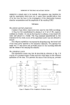
188 JOURNAL OF THE SOCIETY OF COSMETIC CHEMISTS are six switches, one for each odorant stream. Each switch operates on the following principle. The carrier gas divides at a T junction one branch of which leads to a vent while the other leads to the nozzle and the frog. Odorant is introduced into one or other branch of the T by means of a movable, loose-fitting inner tube. It is swept by the carrier either to vent or to the nozzle according to which branch the orifice of the odorant tube is moved into. The switches are designed so that each can be actuated independently of the others. Carrier gas flowing at 100 ml min -x splits into six radially disposed ducts. Each of these then divides at one of the abovementioned T junctions. Therefore 100/12 ml min -x gas issues from each of the 12 branches of the T's. Six of these streams recombine as they enter the nozzle which therefore delivers 50 ml min -x, while the other six lead away to a vent. Odorant streams not being applied and escaping at the vent are prevented from entering the room by an extraction duct. The movable, loose-fitting inner tubes which convey odorant into branches of the T's are stainless steel tubes of outside diameter 0.3 mm. They are moved parallel to their axes by means of pistons which are fixed to them and which run in cylinders. The cylinders are each connected at one end to a source of compressed air or to suction. The change from compressed air to suction is made by solenoid valves which are actuated according to a preset programme by a timing device. The nozzle of the applicator is designed to ensure good mixing of the odorant into the carrier stream. At first various designs were tried in which baffles were inserted in the nozzle to break up the flow Surprisingly these did not bring about the desired mixing. The best way was found to be to rely on diffusion and the problem was simply and effectively solved by extending the 1 mm bore outlet tube from 1 cm to 3.5 cm in length. The fact that the gases were not mixed properly in the original 1 cm long outlet tube was revealed by means of the vapour monitoring system described below. Monitoring system for the odour stimuli (4) This part of the apparatus is shown diagrammatically in Fig. 5. It is used to indicate the concentration of organic yapours in any particular locality such as in the stream issuing from the applicator jet. It consists essentially of a short probe tube connected directly into a standard flame ionization detector (fid) supplied by Pye Unicam Ltd. A sample of the vapours to be tested is drawn continuously into the fid through the probe by applying suction to the fid outlet. The probe tube is 4 cm long and 0.4 mm outside
Purchased for the exclusive use of nofirst nolast (unknown)
From: SCC Media Library & Resource Center (library.scconline.org)