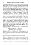
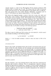
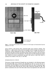
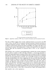
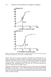
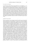
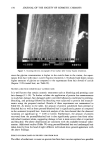
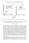
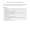
SPF EVALUATION 141 SUBSTRATE PREPARATION The substrates used for testing were the surgical adhesive tapes Transpore © and Blen- derm © (3M Co., St. Paul, MN). The tapes were mounted in plastic 35-mm photo- graphic film slide frames. Transpore © is UV-transparent with machined perforations that provide a uniformly "bumpy" surface topography. According to the manufacturers, Blenderm © tape is identical in composition to Transpore ©, but it does not have perfo- rations and therefore has a relatively smoother surface than Transpore. e Sunscreens were applied to the non-adhesive side of the tapes at an application rate of 2 •l/cm 2 (16.6 -+ 0.2 •1 per slide) by spreading the sunscreens onto the tapes (using a latex-gloved finger) in a circular pattern for 30 seconds with the top of the slide frame off. The researcher subjectively determined the 30-second spreading time to be the amount of time required to sufficiently spread the sunscreen evenly over the slide. The other half of the slide frame was then replaced. EQUIPMENT The experimental setup consisted of a 150-watt xenon arc solar simulator (model 1148, Solar Light, Philadelphia, PA) with the appropriate filters (UG11 and WG 320, 1 mm thickness) to approximate terrestrial sunlight, a radiometer with response characteristics approximating the human erythemal action spectrum (model 3D, Solar Light, Phila- delphia, PA), an analog to digital interface (A/D, PE Nelson, Cupertino, CA), and a }xVAX li © computer (Digital Equipment Corporation, Maynard, MA). The spectral output of the solar simulator and the response curve of the radiometer were determined by the manufacturer (10). The model 3D radiometer was modified to increase the sensitivity five times by changing the feedback resistor in the operational amplifier to 5 M• as described by Cole and Van Fossen (6). The light source was placed at a distance of 20 to 40 centimeters from the detector head, depending on the intensity of the output of the lamp. The solar simulator output was directed onto the surgical tape, which was placed directly in front of the 3D radiometer's ultraviolet B (UVB) detector head. The detector head was mounted in a frame fitted with a 7 mm slot (Figure 1), allowing only 7 mm sections of the sample to be irradiated and transmission detected at a time. The detector head was connected to the 3D radiometer via its amplifier circuit, which was used to drive the signal to the A/D. DATA COLLECTION Since the slot for the detector head was 7 mm wide, five discrete regions on the 35 mm slides were possible for transmission readings however, only readings from the center three regions were used to calculate the average percent transmission to ensure that the most uniform film of sunscreen was read (Figure 1). Once the tape was mounted in the slide frame, the percent transmission of light through the untreated tape was measured. In order to correct for the variations of the light source, which fluctuated with time, a reading of the intensity of the light source was taken before each of the three sections of the slide was read. The percent light trans- mission was made in the following order: baseline, attenuated light source intensity, slide position one, attenuated light source intensity, slide position two, attenuated light

142 JOURNAL OF THE SOCIETY OF COSMETIC CHEMISTS )erector Head Slide - Vertical S• Detector Head Front View Side View ! To 3D meter Figure 1. Slide frame holder assembly. Slides are placed in the slide support and measurements of percent transmission are made. source intensity, slide position three, attenuated light source intensity, baseline. The baseline (i. e., dark current) values were then averaged, and this average was used for the calculations. When measuring the output of the light source, a brass screen filter (3:1 attenuator) was placed in front of the detector head so that the intensity value was within the detection limits of the 3D radiometer. The data from the slide measurements above were collected as percent transmissions that were then used as a basis from which to calculate the estimate of the static in vitro SPF. DETERMINATION OF IN VITRO SPF The percent of light transmitted through tape was calculated in the following manner: the attenuated light source intensity was multiplied by three (to account for the 3:1 attenuator) then the baseline was subtracted from both the value of attenuated light source intensity (times three) and the value of light transmitted through the tape. The percent transmission for each of the three slide sections was expressed as the ratio of the
Purchased for the exclusive use of nofirst nolast (unknown)
From: SCC Media Library & Resource Center (library.scconline.org)