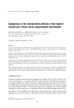
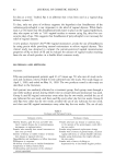
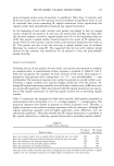
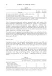
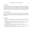
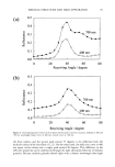
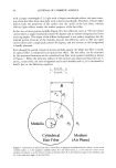
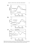
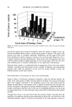
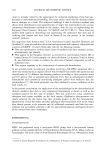
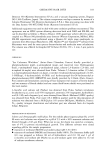
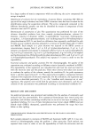
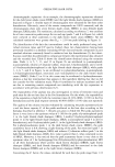
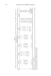
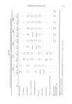
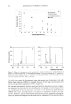
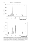
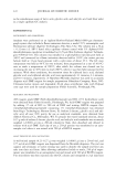
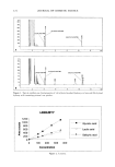
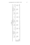
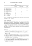
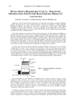
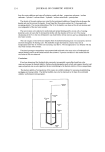
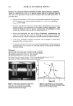
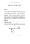
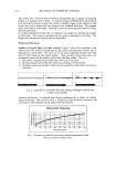
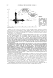
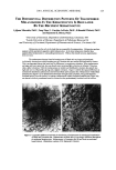
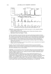
136 JOURNAL OF COSMETIC SCIENCE however, they utilized a different relationship to define luster as shown in Equation 2., where W•/2 represents the width of the specular peak at half of its maximum intensity. The results were generally consistent with the literature data and visual observations. It was shown that: Repeated measurements of various tresses of untreated hair yielded the following values of luster parameters for exposure settings of f8 and 1/13 s: Lst,,,,,, = 0.71 _+ 0.025 and LRot, t, ins= 0.027 + 0.002. Piedmont, Light Blonde, Light Brown, Medium Brown, and Dark Brown Hair showed a gradual increase in luster proportional to the content of melanin pigmentation. Light colored hair displayed clearly two specular reflection bands corresponding to the front and back face reflections from hair fibers as reported earlier [1,2]. Silicone and hydrocarbon oils, such as Phenyl Trimethicone, Amodimethicone, and Castor Oil, increase the luster of hair by enhancing the contrast between specular and diffuse areas on hair. Phenyl Trimethicone was found to be the most effective treatment. Luster can be increased by deposition of polymers, such as hairspray or styling resins, forming thin films on the hair surface. A controlled reduction in hair luster can be achieved by deposition of various amounts of micronized ZnO, which increases the width and intensity of both specular and diffuse reflection from hair. References: [!] R.F. Stature, M.L. Garcia, and J.J. Fuchs, d. Soc. Cosmet. Chem., 28, 571-599 (1977). [2] R.F. Stature, M.L Garcm, and J.J. Fuchs, d. Soc Cosmet. Cbem., 28, 571-599 0977). [3] W. Czcpluch, G. Hohm, and K. Tolkicbn, d. Soc. Costact. Chem., 44, 299-318 0993). [4] H.K. Bustard and R.W. Smith, htt. d. Costlier. Sci., 12, 121-133 0990). [5] C. Reich and C.R. Robbins, d. Soc. Cosmet. Chenl., 44, 221 0993). [6] T. Maeda, T. Hara, M. Okada, and H. Watanabe, 16 th IFSCC Congress, New York, 1990, Preprints, Vol. I, p.127. [7] C. Scanavcz, M. Zoega, A. Bm'bosa, and I. Joekes, d. Cosmet. Sci., 51,289-302 (2000). [8] Available l¾om The University ofTcxas Ileahh Scicnce Center in San Antonio. ! 1,50 0 0 10 20 30 40 Distance (rnrn) Figure 1. Digital image obtained for untreated dark brown hair. The red lines illustrate the image analysis procedure employed to determine light intensity as a function of tress length. Figure 2. Light distribution curve showing light intensity (luminarice) as a function of distance along the hair tress for two different tresses.

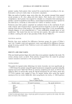
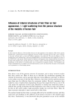
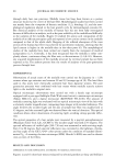
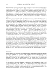
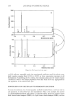
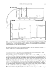
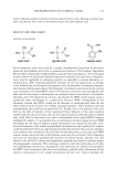
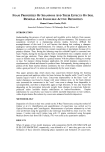
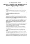
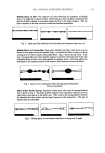
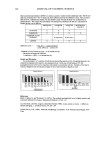
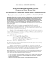
2001 ANNUAL SCIENTIFIC MEETING 137 REAL TIME OBSERVATION OF INTERACTIONS OF HAIR SPRAYS WITH HUMAN HAIR Yash Kamath, Ph.D and Xuemin (2hen, Ph.D. TRI/Princeton, Princeton, NJ 08542 Introduction Hair sprays occupy an important position in the world of styling products. These consist of a polymer formulated in a carrier with appropriate solvents, which can be converted into an aerosol. The particles of the spray when delivered to a hair assembly will form a uniform film on the surface of fibers which becomes unstable with time to form small droplets. These droplets will move along the fiber and coalesce to form larger drops. These droplets ultimately form deposits after the evaporation of the solvent. The nature and the location of these deposits play an important role in the efficacy of the spray as a styling medium. The nature of the final deposits can be altered by changing the properties of the liquid such as surface tension and viscosity and the solvent composition. This paper is aimed at understanding the fundamental aspects involved in the interaction of sprays with hair fibers. We have investigated the behavior of a holding spray and a shine spray. An attempt has been made to explain the observed behavior on the basis of the physicochemical principles involved in the interaction of thin liquid films on a solid surface. Experimental Materials: In this work we have used a commercial "holding spray" and a "shine spray" on European dark brown hair. Method: We have developed a PC-based imaging system to record the real time interaction of a spray on hair fibers (Figl). The system consists of a high speed digital CCD camera with a zoom lens, a power supply, an image acquisition board, a pentium II computer, a light source and a fiber mounting assembly. Board Hmr•pr•y .,,.:,.:'."? • ,, .,...:,.::'5'5!':'i:!,? •ix•E•a•,•,,• •Imr•ib•(,) 0•.•Lo• a Fib•Mount•g •s•bly Pentium III I Computer i Fig. 1 Schematic diagram of the PC-based imaging system.
Purchased for the exclusive use of nofirst nolast (unknown)
From: SCC Media Library & Resource Center (library.scconline.org)