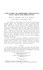
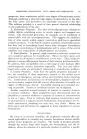
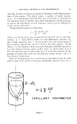
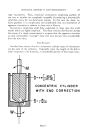
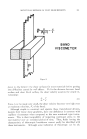
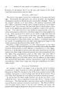
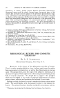
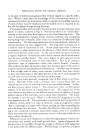
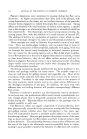
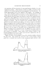
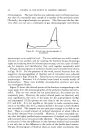
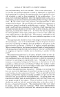
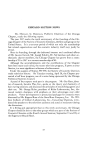
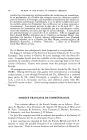
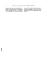
ROTATIONAL METHODS OF FLOW MEASUREMENTS 289 type viscometers. Thus, rotational instruments employing paddles of one sort or another are completely incapable of producing a theoretically valid flow curve for non-Newtonian liquids. In this case the shear ve- locity gradient is so complicated and undefinable that any description of apparent viscosities in relation to shear rate is illusory. Instruments employing small bobs suspended in large cups also yield results which are highly empirical. The shear velocity distribution during the course of a single measurement is so great that the apparent viscosity at some intermediate "average" shear rate may deviate very considerably from the true value. END EFFECTS Another basic source of error in concentric cylinder types of viscometers are the ends of the cylinders. Especially when the length of the bob is small compared to the diameter, a considerable portion of the torque meas- M CONCENTRIC WITH END dv W r •'• = r tQn•, CYLINDER CORRECTION Figure

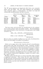
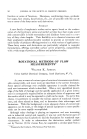
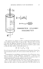
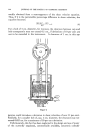
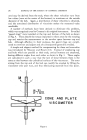
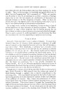
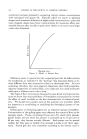
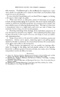
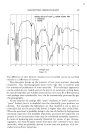
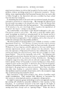
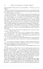
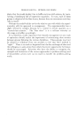
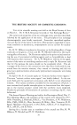
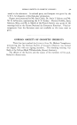
290 JOURNAL OF THE SOCIETY OF COSMETIC CHEMISTS ured may be derived from the ends, where the shear velocities vary from low values (zero at the center of the bottom) to maximum at the outside diameter of the bob. Again, a distribution of shear velocities is obtained, and the associated distribution of viscosities makes the measured value unreliable. A number of methods have been devised to eliminate this problem, which was recognized even by Couette in his original instrument. So-called "guard rings" were installed at the top and bottom of the bob as shown in Fig. 4. They absorb the torque imparted to these areas by the rotating cup and restrict the measurement to the annular space between cup and bob. Although effective in their purpose, the guard rings are compli- cated to construct and adjust and are consequently generally avoided. A simple and elegant method for compensating for these end anomalies was introduced by Mooney and Ewart (12). Instead of employing cup and bobs which are parallel at their ends, conical bottoms are employed, having different angles from each other as shown in Fig. 5. These angles are calculated in such a way that the rate of shear between them is the same as that between the cylindrical surfaces of the viscometer. The error arising from the top end of the bob can readily be avoided by filling the viscometer only part way, and thus eliminating material from this point. Wr tan • CONE AND PLATE VISCOMETER Figure 6.
Purchased for the exclusive use of nofirst nolast (unknown)
From: SCC Media Library & Resource Center (library.scconline.org)