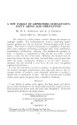
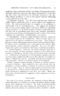
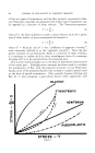
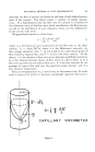
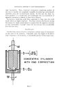
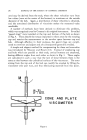
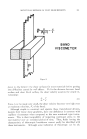
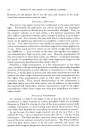
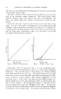
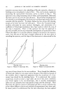
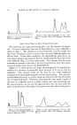
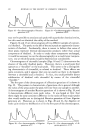
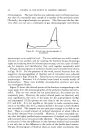
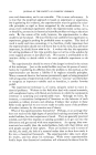
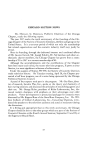
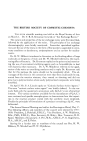
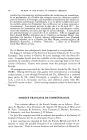
ROTATIONAL METHODS OF FLOW MEASUREMENTS 291 (]]ONE AND PLATE VISCOMETER It is perhaps somewhat surprising that this simple expedient of conical bottoms was not employed earlier. Perhaps even more surprising is the fact that this principle was not used until recently in commercial viscom- eters to eliminate shear velocity distributions in a simple rotational in- strument. Thus, by employing a plain bottom plate and a bob of low angle, while simultaneously eliminating the cylindrical portion of the in- strument, the cone and plate viscometer illustrated in Fig. 6 is evolved. Properly constructed, this instrument has the feature of providing a con- stant shear gradient throughout its measuring surfaces, since: dv rl4/ - K (10) dr - r tan a where////is the rotational velocity of cone or plate, a is the angle between the two surfaces and K is a constant. It will be noted that a requirement of the geometry of this system for successful operation is that the apex of P TRANSLATIONAL VISCOMETER Figure 7.

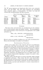
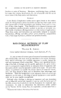
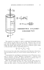
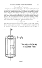
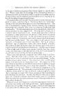
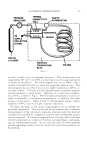
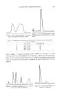
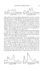
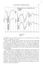
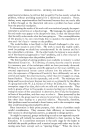
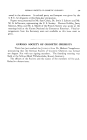
292 JOURNAL OF THE SOCIETY OF COSMETIC CHEMISTS the cone must lie in the plane of the plate. This limits a to some minimum value if extreme precision in machining and readjustment of the relative position of plate and cone in the assembled instrument, after cleaning and refilling with the measuring liquid, is to be avoided. OTHER CONSTANT SHEAR GRADIENT VISCOMETERS If, instead of rotating either the cup or bob of a concentric cylinder vis- cometer, the bob is translated axially, an instrument with relatively con- stant shear gradients can again be obtained which is related to some of the rotational instruments both in general appearance and in theoretical functioning, as shown in Fig. 7. These instruments of necessity are very low shear velocity devices since the bob cannot be translated over a con- siderable distance. They can be of relatively simple construction and consequently are of considerable utility in some instances. Provided, again, that the clearance between cup and bob is kept relatively small, the shear velocity gradient is a linear function from cup to bob surface. If F is the velocity of translation, the shear velocity has the simple function: dv 1• I .• - (ll) dr- Ro - R• zXR Two major variations of this type of instrument are feasible. In one, where materials of very high viscosity, such as pitch, are to be measured, the bottom of the cup may be omitted, and the stress applied directly to the bottom of the bob (13). For more fluid materials, this is no longer applicable, and the bob must be suspended in the cup. Since in this case the cup is closed at the bottom, the bob will displace a certain volume of the liquid as it moves up or down. The shear velocity gradient can conse- quently become complicated where a capillary type flow pattern in the annular space between cup and bob is superimposed upon the linear gra- dient. However, this di•culty has been substantially eliminated by the author by substituting a thin cylindrical shell for the solid bob. The liquid volume displacement becomes negligible under these circumstances and a substantially linear shear velocity gradient is established. Instru- ments of this general type are capable of measuring viscosity in the ultra- low shear velocity range down to as low as one millionth of a reciprocal second (14). At the other extreme, another instrument, working on the translation principle, is capable of yielding measurements in the ultra high shear velocity range of up to 50,000 sec. -•. This is the Band Viscometer (15), shown in Fig. 8, consisting of two closely spaced shear blocks between which a thin, flexible band carrying the test material is pulled. Hydrodynamic forces during a measurement maintain the band centered accurately be- tween the two shear blocks, allowing the use of extremely small clearances
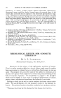
Purchased for the exclusive use of nofirst nolast (unknown)
From: SCC Media Library & Resource Center (library.scconline.org)