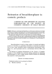
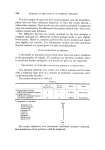
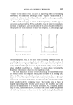
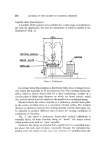
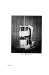
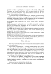
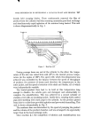
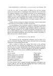
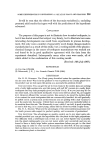
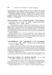
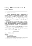
Figure 7 Planetary mixer Facing page 235

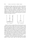
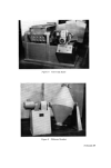
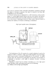
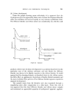
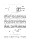
MIXING AND DISPERSION TECHNIQUES 235 impeller will merely act as a circulating pump causing very violent but not very effective movement of the liquid in the tank. On the other hand, when dispersions of high viscosity are being processed, considerable inter- particle shear occurs in the immediate vicinity of the rotating impeller and although the high viscosity could result in "lazy" flow in the tank, in many cases there is sufficient movement to enable the material to be circulated adequately. The extreme case occurs when the viscosity is so high that only a "pocket" of liquid is agitated in the immediate vicinity of the rotating impeller and the rest of the material is immobile thus preventing circulation. It should be mentioned that the dispersion of high viscosity systems at high disc speeds involves correspondingly high power and in certain applications, power of up to 25 hp may be required by batches of 20-50 gal. Planetary mixers Mixers of the type illustrated in Fig. 7 are frequently used for paste or ointment-like materials. The machine comprises stationary, removable containers into which is introduced a slow speed, waltzing blade system and usually a scraper to clean the inner edge of the vessel. This type of machine is widely used for a variety of different applications, from the mixing of ointments to the manufacture of adhesive bandages they are even used in the pharma- ceutical industry for dry mixing and granulation of powders. Bearing in mind the low speed and comparatively large blade clearances in this type of machine a higher shear rate, such as occurs in the Universal mixer described later, does not take place and it is unlikely to be suitable for the breaking down of heavily agglomerated solids. The planetary machine should thus be considered as a satisfactory mixer rather than as an efficient disperser. Universal double 'Z' blade mixers Fo• medium to high viscosity systems, double 'Z' blade mixers, as shown in Fig. 8, are widely used. Basically, these comprise a shaped trough with saddle centre, the mixing action taking place as the result of the rotation of two slow speed shafts on to which are mounted Z-shaped mixing arms, the edges of which are in close proximity to the internal tank surfaces. The two shafts are normally run at differential speeds, this resulting in a squeezing action of the processed materials between the two approaching blade surfaces. A number
Purchased for the exclusive use of nofirst nolast (unknown)
From: SCC Media Library & Resource Center (library.scconline.org)