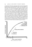
I. Soc. Cosmet. Chem., 24, 593-605 (August 19, 1973) High-Accuracy Blend Control JOHN D. POMFRET, B.A.* Presented December 11, 1972, New York City Synopsis• Early techniques for COMPONENT BLENDING required extra mixing and storage tanks, required frequent feblends, and, in general, were not very satisfactory. Improved MEASUREMENT and DIGITAL CONTROL techniques have resulted in in- line blending schemes that offer significant time and money savings. Three industrial blending situations are described which demonstrate the advantages of in-line blending. These are bulk ingredient blending, aerosol product blending, and wet-dry ingredient blends. Additional commentary on measurement techniques is included in an appendix. INTRODUCTION Traditionally in the cosmetics industry, as well as others, component mixing has been accomplished on a batch basis in mixing tanks. Individual compo- nents in a mixture, or blend, are batebed independently into a tank with mixing accomplished by circulating the contents. Tests are then run on the mixture to determine if it is within specifications. As often as not, test results dictate adding additional ingredients to increase the quality •of the mixture, and occasionally batches must even be recycled to meet final specs. Not only is this method time-consuming and inefficient, but tank require- ments are high and inflexible. Expensive mixing tanks are required, and fin- ished product storage must be available for each of the many varieties blend- ed. A long time is required to make a blend, and without finished storage, a manufacturer would run the risk of not being able to provide, within a reason- able length of time, the products required by his customers. EARLY T•.cm•qm s The first significant attempts at improving on this method of batch blend- ing were meehanieaI systems introduced on a limited seale in the 1940's. •The Foxboro Co., Foxboro, Mass. O•'035. Present address, Applicon, Inc., Bedford, Mass. 01780. 593

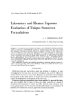
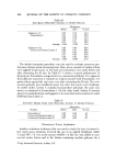
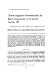
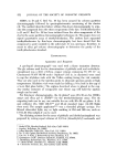
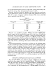
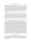
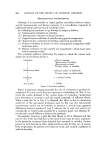
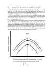
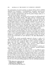
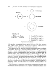
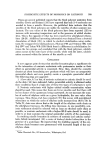
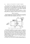
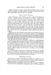
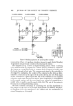
594 JOURNAL OF THE SOCIETY OF COSMETIC CHEMISTS The measurement devices employed in these systems were positive dis- placement meters. These meters, which are still used today, contain a set of gears which rotate at a speed proportional to the volume of fluid passing through the meter. Because each rotation of the gear shaft represents a fixed quantity of fluid, it was possible to devise a system whereby a differential gear was used to compare measurement and set point. These systems, though cumbersome, expensive, and difilcult to maintain, added important new features to blending. For the first time, very accurate ratioing of the various components in a blend was done on a volumetric basis. ]•IGITAL MEASUREMENT About 12 years ago a more economical and simpler device was introduced to provide quantitative ttow measurement. This device is the turbine flow transmitter, or turbine meter. Its operation is shown in Fig. 1. PERMANEN_• MAGNET ROTOR AMPLIFY SHAPE ' X'X'FLOW TUBE Figure 1. Turbine flow transmitter operation (simplified) A freely balanced multiblade rotor assembly is located in a straight flow tube. Liquid flows through the tube, displaces the blades, and rotates the assembly. A permanent magnet imbedded in the flow tube creates a magnetic field which is deflected each time a blade passes through it, inducing a small millivoltage signal. Continuous flow through the tube produces a train of pulses proportional to the volume of flow. The electronic pulse train, when amplified and shaped, is a quantitative measurement signal which can be used in electronic comparators similar in function to the comparison techniques of the earlier mechanical system. Turbine meters and positive displacement meters, besides producing simi- lar quantitative type measurements, have another characteristic which, is, in
Purchased for the exclusive use of nofirst nolast (unknown)
From: SCC Media Library & Resource Center (library.scconline.org)