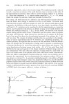
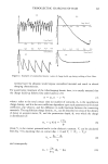
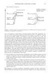
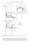
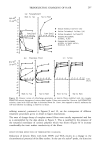
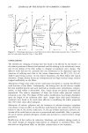
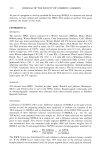
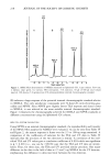
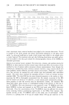
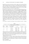
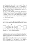
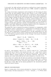
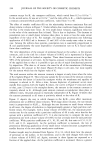
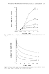
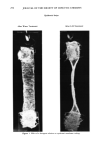
194 JOURNAL OF THE SOCIETY OF COSMETIC CHEMISTS REDUCTION Hair reduction was performed by the use of: (1) tetraukis(hydroxymethyl)-phosphonium chloride-P(CH2OH)4 + C1- (THPC) (0.2 M solution in sodium acetate buffer at pH = 5.2, liquor/hair = 50, 15 minute treatment followed by either 1 minute H20 rinse or 3 minute 2% H202 treatment and H2 ¸ rinse) and (2) thioglycolic acid- HSCH2COOH (TGA) (0.5% solution of TGA was adjusted to pH = 9.2 using NaOH, liquor/hair = 50. Hair tresses were treated for 15 minutes at 37øC. Then they were either only rinsed with H20 for 1 minute or immersed in 2% H202 solution followed by 1 minute rinse with water). BLEACHING AND DYEING Bleaching was performed with a peroxide-based commercial product (Clairoxide, © Clairol Inc.) for 1 hour at room temperature, following the instructions provided with the product. The tresses were then rinsed and dried. Commercially available oxidative haircolors in light and dark shades (Nice'n Easy © #99 and #121, respectively, Clairol Inc.) were used according to the instructions given by the manufacturer. They were applied to hair for 20 min., followed by rinsing with water for 1 minute. RESULTS AND DISCUSSION GENERAL COMMENTS Typical examples of unsmoothed kinetic curves of charge build-up during rubbing of hair fibers in the direction from root to tip or from tip to root are shown in Figure 2. One general feature of the charging process is that the electrical breakdowns of the surrounding atmosphere limit the surface charge densities to less than 7 ß 10-9 C/cm 2. This is illustrated by the charging characteristics shown in Figures 2a and 2c. The recorder trace presented in Figure 2a corresponds to very fast positive charging. Three contacts between the rotating cylinder and the fibers produce the maximum charge density, while the fourth one results in electrical breakdown and reduction of accu- mulated tribo-charges. Charge buildup represented by the curve shown in Figure 2c is slower but enough to cause the electrical breakdown after the threshold value of charge density is reached. The kinetic curve presented in Figure 2d illustrates the case in which the negative charge density on the fiber surface does not reach a value sufficiently high for electrical discharge. In the case of treated fibers, we have occasionally observed initial slow positive or negative charging followed by charge reversal as is indicated by the data in Figure 2b. The reasons for such behavior are not clear. It should be noted, however, that the sliding contact between the fibers and the probe might involve, apart from electron or ion transfer, additional processes affecting tribocharging, such as: (1) Mass transfer between the contacting surfaces leading to the modification of their electrochemical potentials. (2) Surface abrasion. It is plausible that the surface layers of the polymer film or surface of the hair epicuticle might be characterized by a different work function value as compared to the bulk material (12). This could happen, for example, as a result of chemical reactions of the surface groups with oxygen. Subsequent removal of the

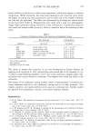
TRIBOELECTRIC CHARGING OF HAIR 195 Time [min] i i i i 0.1 0.2 0.3 0.4 0.5 (b) T•me [m•n] i i i i 0.1 .... 5 0.1 0.2 0.3 0./• 0.5 Time [min] (c) 0.1 0.2 0.3 0./• 0.5 4j• , I I J. me [mJ.•] '• Ik (d) Figure 2. Examples of unsmoothed kinetic curves of charge build-up during rubbing of hair fibers. external layer by abrasion would expose unoxidized material and result in altered charging characteristics. For quantitative treatment of the tribocharging kinetic data, it is usually assumed that the charge build-up follows first-order kinetics (23): tr = tr• (1 - e -kt) (7) where t refers to the total contact time (or number of contacts), tr• is the equilibrium charge density, and k is the rate coefficient dependent upon such parameters as frictional coefficient, slip velocity, and the difference in work functions between the contacting materials. The equilibrium charge density, try, can be described in terms of the density of donor or acceptor states, N, and the penetration depth, t•, over which the charge is distributed (2): 2 VcE tr• = qNqs - (8) where Vc is the contact potential and ½ is the dielectric constant. Vc can be calculated from Eq. 5 by assuming that on contact Apt = 0 and Vc = (Vsl - Vs2): Vc - (9) and consequently - (02 - 0•) (10) tr•
Purchased for the exclusive use of nofirst nolast (unknown)
From: SCC Media Library & Resource Center (library.scconline.org)