56 JOURNAL OF THE SOCIETY OF COSMETIC CHEMISTS boundary equation is a straight line frictional relationship between the bulk solid and the wall material. Using these equations and certain simplifying assumptions, particularly that {1) the stress and velocity tensors are in line and are not coupled, {2) the velocities are so small that inertial effects need not be considered, and {3) the stress field is radial within the material, Jenike was able to formulate a design method for axially symmetric and two dimensional hoppers. He also devised a means of testing the materials to provide the material and boundary equations. The testing method is also an excellent means of detecting changes in a material property during a manufacturing process. His design method has been widely used for a number of years and of the various theoretical approaches {5-9) to the design of hoppers, it is generally considered to be the best and is the most universally accepted. Details of the design method are given more fully by Farley {10), and Jenike (5, 11). DISTINCTION BETWEEN FAILURE AND FLOW Many workers in the field of particle mechanics do not accept the validity of all Jenike's assumptions. However, it is generally accepted that the design method combined with the material testing method give a conservative result which works, in the engineering sense, in describing the conditions up to the point of incipient failure. As it is not proposed to discuss all the assumptions, two only will be considered here those of a homogeneous material or single phase system, and negligible inertial forces. It is obvious when the flow is fully developed, that J enike's model can no longer apply in the vicinity of the orifice because dilation takes place and the interstitial air becomes the continuous phase. The material also moves relatively fast in the orifice region and the inertial forces became significant compared with the other forces in the system. It can be said, therefore, that although considerable progress has been made in the methods of designing a hopper for mass flow, the same cannot be said for predicting the rate of flow from such a hopper. The problem is important from the viewpoint of design of metering and feeding equipment, and as yet no generalized equation for the rate of discharge of granular material has 1)een derived. Many of the equations upon which the designer is forced to

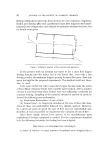
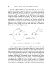
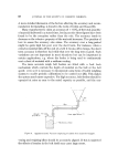
THE FLOW OF PARTICULATE blATERIALS FROM HOPPERS 57 rely, are dimensionally unhomogeneous and the flow rates computed (12) from them can differ by more than an order of magnitude. METHODS OF CAI. CUI. ATING TIlE FLOW RATES OF MATERIALS FROM ttOPPERS Much of the work has been done on the gravity flow rates from hoppers under free discharge conditions. However, most of this has been done using small scale hoppers and results for orifices above 20 mm diameter are exceptional. It is also unfortunate that most of the materials that have been used are rather special in that they are often narrow size cuts and all the particles are the same shape, e.g. seeds and spheres of various types. The correlations that exist in the literature for calculating flow rates can be divided into: (1) empirical equations (3, 13-15), (2) those derived from dimensional analysis (16-18), (3) those derived from fluid analogies (12, 19), (4) those based on the conception of a dynamic arch (20-22} derived from incipient floxv theory, and (5) those based on considerations of the energy (23) of a moving column of material. Of all the analyses, the most interesting is that of Brown (23) who considered the energy of a particle in a stream tube as it moved towards the orifice. The assumption of radial flow was also made this was justified by the experimental work of Brown and Richards (24, 25}. Brown's ap- proach is fundamentally different from those of other workers in that it emphasises the essential two phase nature of the system. He assumed that the total kinetic and potential energy of the particles in a stream tube was D---k a minimum at the surface R -- and, by neglecting any change in 2 sin [• bulk density in the orifice region, he was able to show that Up, the par- ticle velocity on the plane, is given by, g (D--k) cos0 P 2 sin [I which integrated, gives for the flow through the orifice, 4Q (1--cos p •r (D--k)2 [g (D--k]] ø's 2 ø'• sin "s•
Purchased for the exclusive use of nofirst nolast (unknown)
From: SCC Media Library & Resource Center (library.scconline.org)