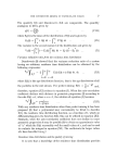
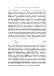
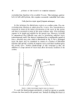
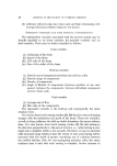
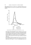
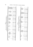
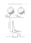
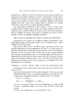
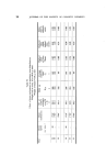
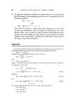
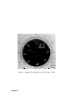
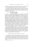
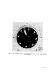
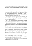
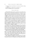
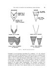
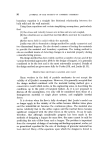
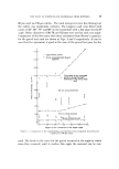
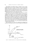
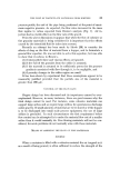
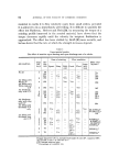
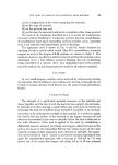
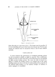
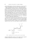
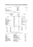
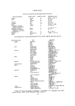
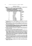
THE FLOW OF PARTICULATE MATERIALS FROM HOPPERS 65 (1) the configuration of the vessel containing the material, (2) on the type of material, (3) on the particle size, and {4) on the time the material is allowed to consolidate after being aerated. The basis of the technique described here is to aerate the material con- tinuously without fluidizing it. Continuous aeration prevents consolidation. If consolidation takes place channelling and bad aeration occur, especially if air is not injected until immediately prior to discharge. The apparatus used is shown in Fig. 8 and the results obtained by injecting air into a calcite which would, after 24 h consolidation, normally support an arch in the hopper of 0.513 m/diam. are shown in Table I. The method is shown to be effective and it has been found that the material can be discharged on to a belt without excessive flooding, the rate of discharge being controlled by a 'mucon' valve. It is emphasized that at the present time this method can not be guaranteed to work for all cohesive materials. Live storage In very small hoppers, aeration can be achieved by continuously stirring the material, thereby lifting it and continuously moving it through the air so that it remains aerated. Such devices are the basis of some proprietary feeders. Vacuum discharge The strength of a particulate material increases as the particles get closer together and the size of arch the material can support also increases. If material is to flow through a small orifice this arch must be broken by increasing the load on it until its shear strength is exceeded, or by mechan- ical action or by reducing the strength of the material. It is useless to apply the load to the top surface of the material in the hopper because the net effect on the material in the cone is virtually nil for the load is deflected to the walls. However, if the load is applied to the arch by establishing a differential pressure across it two things can happen, either the load on the arch is increased or the interstitial fluid in the surface layers of the arch expands causing particle separation and a decrease in strength. The appar- atus used is shown in Fig. 9. Calcite as used in the aeration experiment was again the experimental material with a vacuum of 113.5 kN m-2 it was moved out of the mass flow hopper and along 1.8 m of 15 mm internal

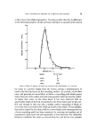
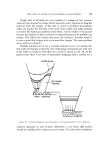
66 JOURNAL OF THE SOCIETY OF COSMETIC CHEMISTS r AIR •,AIR AERATION RING HOPPER 4 ORIFICE DIAMETERS APPROX 1.5-2 ORIFICE DIAMETERS APPROX Figure 8, Air injection system. diam. glass pipe at a rate of up to 3 t h- 1. The hopper must be mass flow. If it is not, funnelling will occur xvhich breaks the vacuum seal. For the same reasons the material must be non-porous which is true of most cohesive materials. Control of flow rate In many instances the performances of continuous metering systems are not as accurate or reliable as might be expected. This is unfortunate coming as it does at a time when there is increasing interest in and demand for high accuracy feeding systems. The cause can often be traced to a failure to consider the feeding system as an integral part of the whole handling system and also to the lack of understanding of the properties of the material being handled, e.g. the material strength, its tendency to aerate, segregate, or consolidate.
Purchased for the exclusive use of nofirst nolast (unknown)
From: SCC Media Library & Resource Center (library.scconline.org)