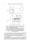
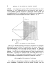
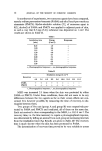
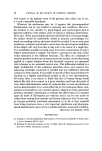
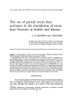
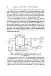
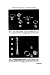
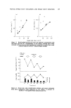
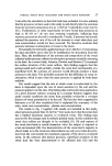
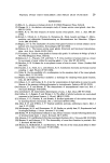
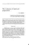
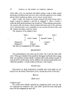
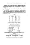
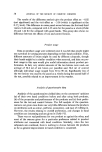
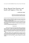
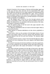
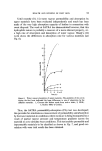
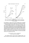
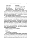
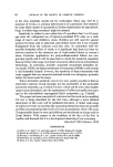
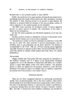
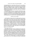
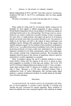
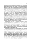
JOURNAL OF THE SOCIETY OF COSMETIC CHEMISTS Figure 1. Sweat collection capsules. A, base of unventilated capsule with top, B. C, ventilated capsule, the inlet and outlet arms are set at an acute angle to promote evaporation. D, top with securing ring, E, fitted when pressure was applied. Figure 3. Spring-loaded pressure applicator. A, screw controlling calibra- tion setting B, marked on barrel of unit C. D, rubber pad which forms exact fit into skin capsule E. F, three springs of varying tensions which fit within the barrel C. Facing page 18

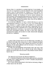
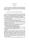
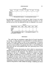
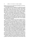
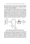
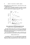
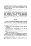
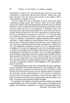
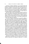
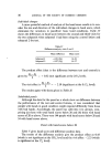
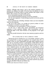
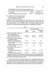
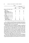
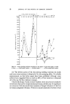
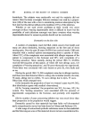
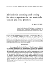
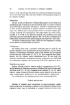
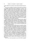
PARTIAL SWEAT DUCT OCCLUSION AND SWEAT DUCT FUNCTION 19 solutes which remained on the skin surface were eluted by washing the skin within the capsule with distilled water these washings were analysed for constituents. During washing the gas flow was stopped and restarted only when the skin had been thoroughly dried. In order to reduce the sweat output, small pressures were applied over the skin during alternate 4 min collection periods. Usually seven collection periods were obtained in each experiment, in this case pressure was applied in collection periods two, four and six. When sweat was absorbed onto filter papers, pressure was applied mechanically over the filter paper with a spring-loaded rubber pad. This apparatus is shown in Fig. 3. When held vertically the pad (D) forms a close fit within the unventilated aluminium capsule (E). The pressure exerted through the pad is determined by the strength of the spring (F) placed within the barrel (C) and also on the scale setting (B) on the barrel. This setting can be adjusted by rotation of the screw (A), so that for each spring a range of pressures can be obtained. N2 • WATER OUT VA POUR INFRA JL A•AL•O ALUMI hilUM SKIN CAPSULE SCREWCAP TItROTTLE A II METER N 2 IN THROTTLE B MANOMETER Figure 4. Diagram of flow system used to measure sweating and to increase pressure suddenly within skin capsule. See text for description of its use. When sweat was evaporated from the skin surface, air pressure within the ventilated capsule was increased by manipulation of two throttles situ- ated in the gas stream before and after the skin capsule (Fig. 4). The flow of gas into the capsule is controlled by throttle A (Fig. 4), when the outflow is passed through route 1, the moist gas passes unimpeded to the infra-red analyser. If the gas is passed through route 2, manipulation of throttle B can reduce the outflow and thereby produce a back pressure within the capsule. Throttle B may be preset so that movement of the three-way tap
Purchased for the exclusive use of nofirst nolast (unknown)
From: SCC Media Library & Resource Center (library.scconline.org)