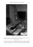
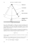
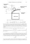
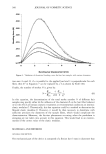
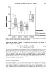
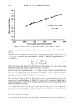
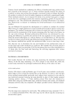
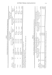
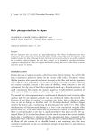
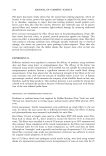
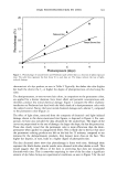
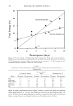
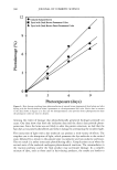
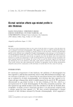
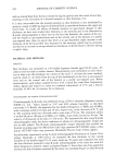
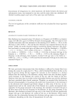
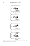
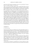
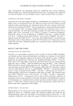
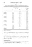
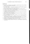
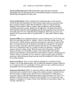
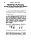
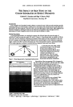
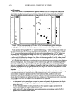
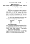
BENDING PROPERTIES OF HAIR FIBERS 359 Unbent Hair Fibre (radius R) Bending bar (radius: r) • I/ Modelized bending bar displacement Bent hair fibre during test Metallic support Figure 3. Equivalent mechanical geometry to model the bending energy. This curve model was checked using experimental data obtained by clamping a flexion bar on a Zwick © tensile machine with an equivalent geometry and bending the previ- ously described samples. The theoretical curves (after adjustment of constant El in Equation 4) fit well with the experimental data of hair fibers having various diameters (Figure 4). When numerically integrating the curve F(8), the bending energy is given by = (5) The most precise determination of the constant • by integration of the function F(•), gave a value of /• = 0.2149 mm -• (6) As a first approximation considering the hair fiber as an isotropic elastic material, the theory of bending for elastic materials can be used. Moreover, if one assumes that all the fibers have the same geometry and the same mechanical behavior, the bending inertia of . cylindrical parallel bars can be calculated from the radius of the bar by using -- I=n 4 (7) In our test, R corresponds to the mean radius of bent hair fibers and n corresponds to the number of fibers bent at the same time. In the case of an elliptical fiber defined by its

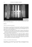
360 JOURNAL OF COSMETIC SCIENCE .035 .030 Z•, .025 • .020 • .015 .010 .oo$ 0 2 4 6 8 10 Bending bar displacement (mm) Figure 4. Validation of theoretical bending curve for four hair samples with various diameters. two axes 2a and 2b, if a is parallel to the applied load and b is perpendicular for each fiber, then/•4 in Equation 7 can be replaced by a3b as shown by Swift (10). Finally, the number of strokes N is given by: N-Ef/e,•-nqTk E I• 4 (8) In this equation, the determination of the total stroke number N of different hair samples may specify either (i) the influence of the diameter R on the hair fiber behavior or (ii) the effects of various cosmetic treatments or environmental conditions on intrinsic elastic modulus E. Theoretically, this last equation could be a method to determine the flexural elastic modulus E. However, it would be then necessary to determine with sufficient precision the diameters of the sample fibers, which would complicate the characterization. Moreover, the friction phenomena occurring when the pendulum is swinging are not taken into account in this equation. This would lead to an overesti- mation of the correct value of the elastic modulus. MATERIALS AND METHODS GENERAL DESCRIPTION The mechanical part of the device is composed of a flexion bar (3 mm in diameter) that
Purchased for the exclusive use of nofirst nolast (unknown)
From: SCC Media Library & Resource Center (library.scconline.org)