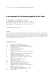
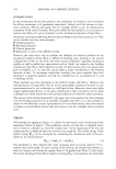
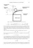
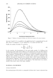
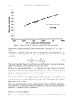
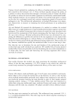
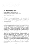
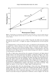
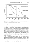
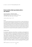
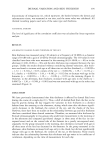
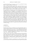
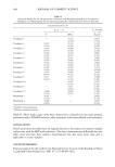
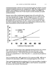
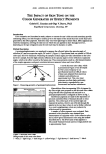
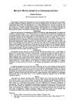
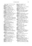
360 JOURNAL OF COSMETIC SCIENCE .035 .030 Z•, .025 • .020 • .015 .010 .oo$ 0 2 4 6 8 10 Bending bar displacement (mm) Figure 4. Validation of theoretical bending curve for four hair samples with various diameters. two axes 2a and 2b, if a is parallel to the applied load and b is perpendicular for each fiber, then/•4 in Equation 7 can be replaced by a3b as shown by Swift (10). Finally, the number of strokes N is given by: N-Ef/e,•-nqTk E I• 4 (8) In this equation, the determination of the total stroke number N of different hair samples may specify either (i) the influence of the diameter R on the hair fiber behavior or (ii) the effects of various cosmetic treatments or environmental conditions on intrinsic elastic modulus E. Theoretically, this last equation could be a method to determine the flexural elastic modulus E. However, it would be then necessary to determine with sufficient precision the diameters of the sample fibers, which would complicate the characterization. Moreover, the friction phenomena occurring when the pendulum is swinging are not taken into account in this equation. This would lead to an overesti- mation of the correct value of the elastic modulus. MATERIALS AND METHODS GENERAL DESCRIPTION The mechanical part of the device is composed of a flexion bar (3 mm in diameter) that

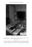
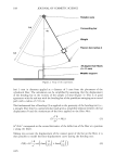
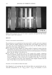
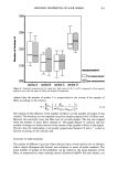
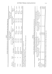
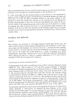
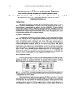
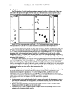
BENDING PROPERTIES OF HAIR FIBERS 361 is linked to two connecting perpendicular bars 30 cm in length. These two parallel bars are fastened at one end to the rotation axis. A 47-g weight is placed between the two connecting bars, thus giving the system its initial inertial energy. According to the geometry of the system, this weight ensures that the bending bar swings with an initial speed of about 1 m/s. Initially, the bar is clamped at an angle of 30 ø from the vertical, and it is manually released without any initial push. The bar can then swing through the rotation axis. Each time the bar reaches its lowest point (i.e., the connecting bar is vertical), it hits the 39-hair-fiber sample (Figure 2). At each hit of the bar on the sample, part of the pendulum energy is lost by elastic bending of the hair fibers. Thus, the amplitude of the swinging pendulum slowly decreases until it stops. An optical sensor placed in the device measures the number of strokes until the pen- dulum stops. In a more recent version, a new optical sensor permits us to measure the speed of the pendulum when reaching the vertical position. The initial speed of the pendulum is Vo = 0.977m. s -• (9) It is then possible to determine precisely the initial energy of the pendulum: 1 2 Ei,it = • mv o • Ei,it = 22.9 mJ (10) SAMPLE PREPARATION In the usual configuration, each sample is composed of 39 fibers of 11-mm length, fixed on a metallic support and spaced 1 mm apart from each other. The sample size was selected in order to take into account the variability of the cross sections of each hair fiber and to achieve the best results in terms of dynamic range. Moreover, the number of fibers was selected in order to ensure a reasonable running time (approximately three minutes per test). Each sample was conditioned for a minimum of twelve hours in a conditioning chamber set to the temperature and relative humidity required for the test. It was then mounted on the pendulum device also located inside the conditioning chamber. If the hair tress was long enough (minimum length of 25 cm), it was possible to obtain a series of four samples composed of hair fibers from the same tress (Figure 5). VERIFICATION PROCEDURES Before measuring any sample, two verification procedures of the apparatus were carried OUU ß The first consists of running a test without any sample in order to ensure that the pendulum can swing through its axis. In this case, an average ofNfr•e = 1000 strokes must be measured. ß The second test corresponds to the evaluation of a reference that is composed of 39 standard nylon fibers (96 lam in diameter) this sample was designed during the validation of the method. The expected reference value is N,y/o , = 115 + 3 strokes.
Purchased for the exclusive use of nofirst nolast (unknown)
From: SCC Media Library & Resource Center (library.scconline.org)