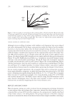
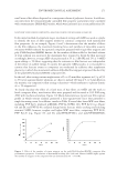
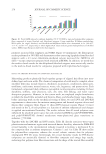
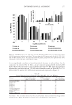
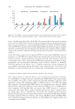
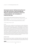
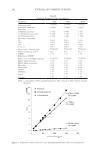
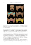
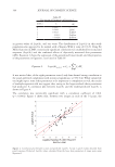
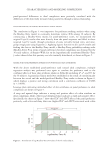
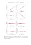
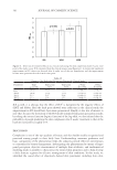
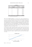
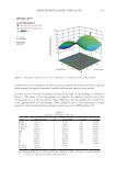
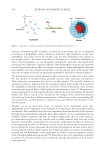
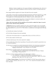
281 Enviromechanical Assessment Additionally, scatterplot correlations between published 50% RH DHSA-AED performance indices (16)—including maximum force response (F1), toughness (i.e., strength to avoid weld ruptures in treated omega loops), #AED, and residual style stiffness (E10/E1)—and results from film-rupture testing with AED are presented in Figure 15. Figure 15A–C relate the work to compress neat and virgin fiber composite films with F1, toughness, and E10/E1 measured by DHSA using fixative-treated virgin tresses that had been shaped into omega loops (13,16). The F1, toughness, and E10/E1 indices were assessed during the primary omega loop compression, whereas #AED includes the quantity of detected emissions from all 10 DHSA compression cycles. Figure 15A and B demonstrates that F1 and toughness correlate linearly and positively with the work to compress neat (R2 =0.87 and 0.84) and virgin fiber composite films (R2 =0.94 and 0.86). In addition, the E10/E1 indicator showed moderate associations with the work to compress composite films (R2 =0.62), but poor correlations with the work to rupture neat films (R2 =0.33) (Figure 15C). Regarding the release of audible energy during film rupture, since #AED from DHSA- AED negatively trends with fixative MW (R2 =0.84), we expectedly found that #AED from DHSA-AED adequately correlates with the work to compress neat (R2 =0.74) and virgin fiber composites (R2 =0.79) (Figure 15D) (16). More interestingly, the #AED captured while rupturing virgin fiber composite films correlated moderately with the work to compress virgin fiber composites (R2 =0.60) however, the #AED liberated by neat films poorly associated with the work to break neat films (R2 =0.26), indicating that only a small number of cracks are needed to initiate structural failure in neat films. In general, DHSA-AED indices correlated better with the requisite work to rupture film-fiber composites—rather than the work to break neat films. The weak correlation (R2 =0.49) between #AED produced in DHSA-AED and #AED liberated in AED with composite film testing is clearly linked to differences in weld density in the current studies, the fixative in film composites formed tortuous seam welds, whereas the fixative in treated omega loops produced distributions of interspersed spot and seam welds. To reproduce similar weld distributions using film composites testing, Figure 15. Correlation of the work required to break neat and composite films with (A) F1 DHSA parameter (B) toughness as measured in DHSA (C) E10/E1 index as measured in DHSA and (D) #AED from DHSA- AED. Note that DHSA measurements were performed on fixative-treated omega loop assemblies (50% RH).

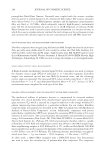
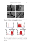
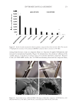
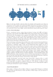
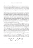
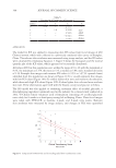
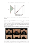
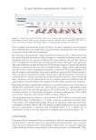
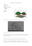
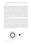
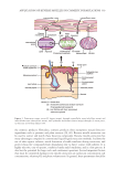
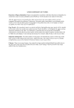
282 JOURNAL OF COSMETIC SCIENCE film composites should be constructed with dilute fixative solutions (e.g., 1.5% [w/w]) and 0.15 g of fiber snippets—as an example, see the SEM micrograph in Figure 16. At lower applied fixative concentrations, the contiguous polymer solution dried and spontaneously developed realistic film discontinuities consequently, the measured #AED in composite film testing better associated with #AED captured in DHSA-AED (R2 =0.77). ONGOING FILM-FIBER COMPOSITE STUDIES: NATURAL BIOPLASTICS To conclude the composite film testing discussion, it is worthwhile to mention that natural fixative polymers have been added to ongoing composite film studies in which the intrinsic durability and fracturing behavior of bioplastics—including cellulose ethers, cationic guars, and biodegradable polyesters—are being examined. In conjunction, supplemental analyses are being used to investigate the possibility that fiber alignment in the film influences the enviromechanical failure response of the composite. Put differently, recent method adaptations incorporate fiber alignment and mechanical anisotropy arguments into the discussion. Mechanical anisotropy is a material property that is likely introduced to the composite film by the ultrafine structure of the hair fiber, wherein hair fibers resist elongation but willingly bend and twist when torque is applied transversely. By way of illustration, Figure 17A models a scenario in which the longitudinal axes of the fibers were aligned with the imposed tensile forces (±F) in distinction, the long axes of hair snippets in Figure 17B were positioned parallel to the plane of the film, but normal to the applied F. Additionally, Figure 17C models a blend of the fiber patterns illustrated in Figure 17A and B, in which the hair snippets formed a crosshatch within the plane of the contiguous polymer film. Lastly, in Figure 17D a small testing sieve was attached to a ring stand and suspended above a Teflon dish containing fresh polymer solution. Several hair fibers were then inserted through the sieve mesh, and the distal ends of the fibers were immersed in polymer solution after drying, the fibers were trimmed at the film surface such that the longitudinal axes of the embedded snippets aligned perpendicularly with the plane of the dried film and applied tensile F. Figure 16. SEM micrograph of a film-fiber composite formed using 0.2 g of 10-mm fibers dispersed in a film prepared with a 1.75% (w/w) imidized p(IB/MA) solution. To create the splayed welds in the image, the composite was deformed 5 mm at 85% RH using a 0.25-inch stainless-steel ball probe and an indexable film support rig—after 15 minutes, the humidity was abruptly lowered to 35% RH to induce a relaxed rubber-to- glass transition in the splayed and cavitated welds. The subsequent micrographs demonstrate the significant tensile forces being exerted on the fibers and interspersed seam welds.
Purchased for the exclusive use of nofirst nolast (unknown)
From: SCC Media Library & Resource Center (library.scconline.org)