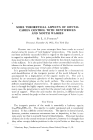
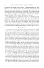
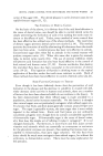
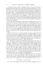
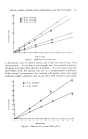
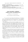
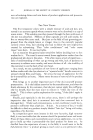
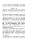
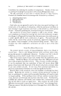
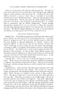
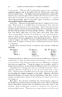
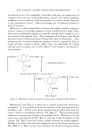
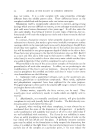
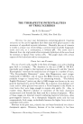
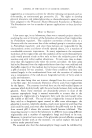
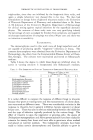
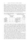
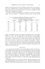
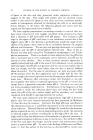
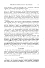
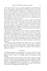
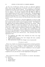
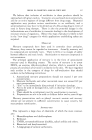
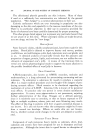
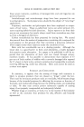
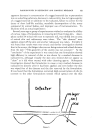
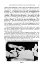
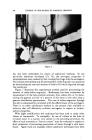
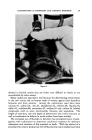
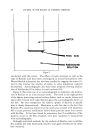
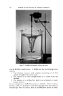
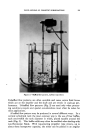
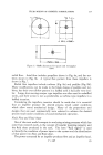
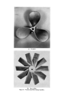
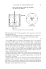
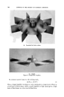
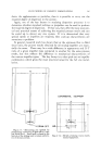
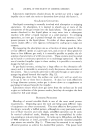
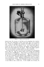
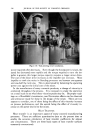
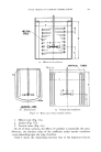
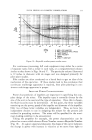
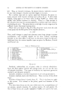
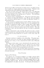
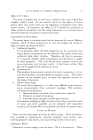
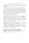
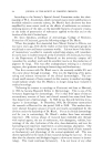
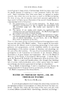
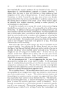
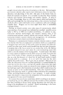
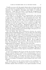
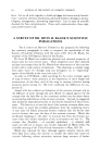
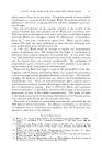
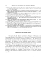
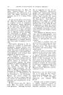
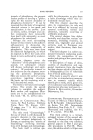
FLUID MIXING OF COSMETIC FORMULATIONS 337 • 1.5w_ L- 2W Figure 5.--Barlie placement for square and rectangular tanks. radial flow. Axial flow includes propellers shown in Fig. 6a, and fan tur- bines shown in Fig. 6b. A typical flow pattern from these impellers is shown in Fig. 7. Radial flow impellers include turbines (Fig. 8a) and paddles (Fig. 8b). Many modifications can be made to the blade shapes of paddles and tur- bines, but their over-all flow pattern in a baffled tank is basically very simi- lar. Large, slow-moving scraper type impellers are often used in unbaffled tanks, and their action is not so predictable as turbine type impellers in a baffled situation. Considering the impellers, mention should be made that it is essential that an impeller produce the desired process result under conditions which allow sound mechanical design. Many of the proportions and designs that are used commercially were selected to achieve the desired process result under conditions of sound mechanical operation. Fluid Flow and Fluid Shear One of the most useful concepts in analyzing mixing processes which has come from research work, is the concept of impeller pumping capacity and the fluid shear produced in the tank. The term "fluid regime" is used to identify the condition of power input to the system and the distribution of that power into flow and fluid shear. The power consumed by an impeller produces flow and an impeller head. P = •H

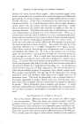
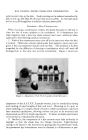
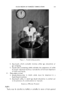
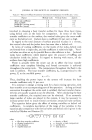
(a) Propeller. "•ib) Fan turbine. Figure &--Typical axial flow mixing impellers.
Purchased for the exclusive use of nofirst nolast (unknown)
From: SCC Media Library & Resource Center (library.scconline.org)