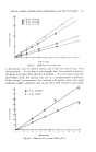
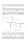
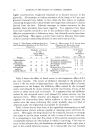
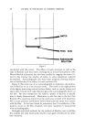
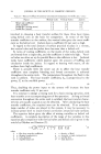
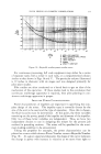
350 JOURNAL OF THE SOCIETY OF COSMETIC CHEMISTS TABLE l--RELATIVE HEAT TI•ANSFEI• COEFFICIENT COMPARED WITH HELICAL COILS Factor Helical Coils Vertical Tubes Jackets Mixer side coefficient 1,0 1.0 0 65 Area available 1.0 0.5 0, 5 Inside film (cooling water) 1.0 0.1 0.5 Inside film (steam) 1.0 1.0 1 0 involved in choosing a heat transfer surface for these three basic types, using helical coils as the basis for comparison. In terms of the heat transfer coefficient on the surface, the vertical tube gives the same coeffi- cient as the helical coil. Jackets have a coefficient 65 per cent as high. In regard to the total amount of surface practical to place in a system, the vertical tube and the jacket have less area than a helical coil. In terms of cooling coefficients on the inside of the tubes, helical coils are formed from a single tube, and the coefficient is relatively high. Verti- cal tubes are often set up for parallel flow so the cofficient is low. Jacketed tanks have coefficients which depend upon the amount of baffling and circulation inside the jacket. In regard to heating with steam, all the surfaces have high coefficients. There is actually little the mixer can do to affect the heat transfer coefficient once complete blending and forced convection is achieved throughout the entire tank. The temperature throughout the fluid in the tank is uniform. The heat transfer coefficient, h0, is proportional to the power, P, to the one-fifth power. ho • p1/• (4) Thus, doubling the power input to the system will increase the heat transfer coefficient only 15 per cent. It is common to design a mixing tank for a basic mixing operation, with heat transfer as an accompanying part of the operation. As long as forced convection throughout the entire tank is satisfied, the heat transfer charac- teristics are usually as good as can be obtained. After calculating the heat transfer coefficient, the required area can be obtained. If an extremely large number of tubes are placed in the system, it may be necessary to increase power level to insure forced convection around all tube surfaces. The equation below gives the effect of mixing variables on helical coil coefficients. A complete description of the range of the variables in this equation plus comparison with vertical tubes and helical coils is given in the article by Oldshue and Gretton (2). where h = film heat transfer coefficient o = density of fluid k -- thermal conductivity u = viscosity at tank temperature d = tube diameter Ce = specific heat D = impeller diameter T = tank diameter

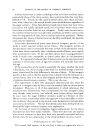
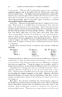
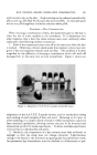
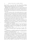
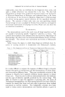
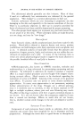
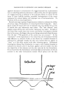
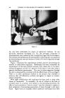
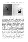
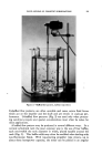
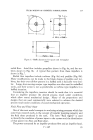
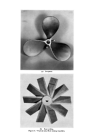
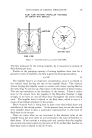
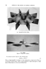
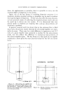
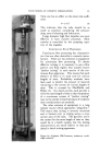
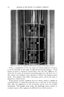
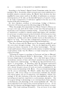
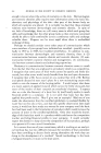
FLUID MIXING OF COSMETIC FORMULATIONS 351 Tube size has an effect on the mixer side coeffi- cient. h ,x 1/"¾/• (6) This indicates that the tube should be as small as practical considering the pressure drop, ease of cleaning and fabrication. Large diameter high flow impellers are most effective in heat transfer processes. Heat transfer is controlled by the pumping capa- city of the impeller. CONTINUOUS FLOW PROCESSES Continuous flow processing has characteris- tics that are often desirable in cosmetic manu- facture. There are two extremes in equipment for continuous flow processing. To obtain effective mixing, it is necessary to use a flow pattern and fluid regime that usually insures "perfect mixing" in each section of the con- tinuous flow apparatus. This means that each element of fluid is in each zone for various lengths of time. Probability methods have been used to predict the amount of material remaining in the system for various lengths of time. This is covered by MacMullin and Weber (1). In a batch system, each particle is in for the same length of time so that the product of a continuous system of "perfect mixing" may not be similar to batch products if residence time considerations are essential. The other extreme of equipment is a long tubular reactor which approaches "plug flow." This means that mixing is severely restricted and is limited only to mixing across a cross section area of the tube. The particles are in the system for the same length of time as they would be in a batch system, but the mixing characteristics are much inferior to that pro- duced in batch mixing apparatus. Figure 16.--Lightnin CM-Contactor, continuous multi- stage contactor.
Purchased for the exclusive use of nofirst nolast (unknown)
From: SCC Media Library & Resource Center (library.scconline.org)