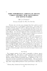
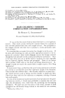
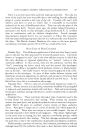
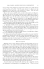
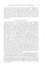
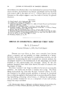
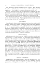
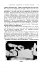
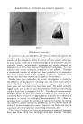
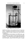
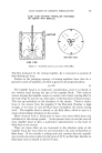
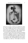
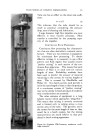
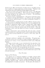
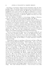
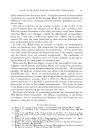
352 JOURNAL OF THE SOCIETY OF COSMETIC CHEMISTS .. ,. •:.•: ..... ß : . :. ,". 4 :•,• • .:' - '.•' • • ß : . ß , :,. •: ..z.: :• '• -•- .:• . • :• ,•.,. : , .•:. •":,.:.:•,., -., • .. • .. ' ' "- .•.: ':: ., • - ...½.:... , .. ... •. .. . • .• .• •:' •. 5" ' . . . :::.•: : , :. ...•. -- •. ,:- : , ß . ".. ' .-... -.: ........... .---.. ......... . .... . : ....... .: : : Figure 17.--Close-up of Lightnin CMContactor• continuous multistage contactor. } roma consideration of the two types of mixing equipment extremes, it can be extended to two types of chemical processing extremes. If' the process involves a chemical concentration, then the only difference be- tween the two types of continuous processing apparatus and batch runs is the volume and residence time required to achieve the desired process result. The product from either continuous system will be the same as those from a batch system. If the process involves residence time as a factor, which is typified by a polymerization in which the molecular size is a function of the residence time, then the application of the continuous system must be carefully scrutinized. The product from either the multistage mixer column, or a tubular reactor will, in general, be different from a batch product.

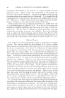
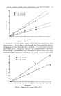
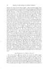
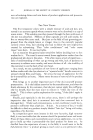
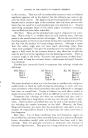
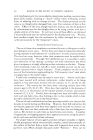
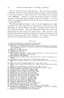
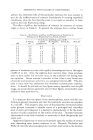
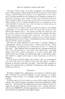
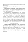
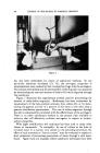
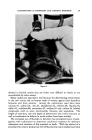
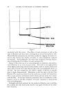
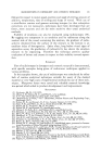
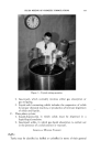
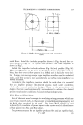
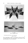
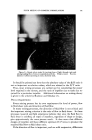
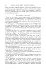
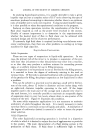
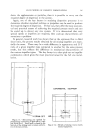
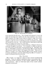
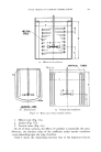
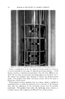
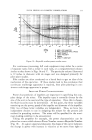
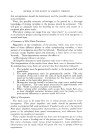
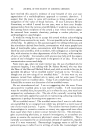
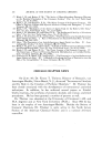
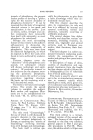
FLUID MIXING OF COSMETIC FORMULATIONS 353 ,•? J•_•] II IIII1 •l•II• ] I JillIll !]! 1[ ....... • .................. •.. ]]•i • [ IllIll I [ J J 111[•• Illll I I I II1[ • • • [ •l [ [ I ••,:'•,TU•,•,• •'-•-- ,•l I I•11111 • • •EuRV•B•I,•I•I • • •,,•,H [[•LI • II11111 I I II1•',• I I I[llllJ ] I[I]1111 r I : •'•1 ' i II !Jill I-• •4•'.. • • ',',II',J', ', ', ', ',',', f:[rl [ I I[1111 • I [•T c ..... [ • , ,• r ] -• [[[][[[ [ [ [][][]•'C••ED•R•EN I IO IO t IO • IO 4 I0 9 [ io 6 D"N• D IMPELLER DIAMETER .).L N IMPELLER ROTATIONAL SPEED e LIQUID DENSITY J.L LIQUID VlSGOSITY P POWER g GRAVITY GONSTANT Figure 18.--Reynolds number-power number curve. For continuous processing, full scale equipment may either be a series of separate tanks with a mixer in each tank, or a compartmented column similar to that shown in Figs. 16 and 17. The particular column illustrated is 12 inches in diameter with six stages and was designed primarily for pilot plant studies. Pilo.t studies are often conducted on a batch basis to get an idea of the mechanism of the operation. If these studies lead to the conclusion that continuous multistage apparatus is required, then pilot planting in con- tinuous multistage apparatus is proper. IMPELLER POWER CHARACTERISTICS Power characteristics of impellets are important in specifying the com- plete design of the mixer. The impeller type is normally chosen by the size of the unit to be used and the type of operation. Once this is chosen, the fluid viscosity must be determined. At this point, the three variables remaining are the power, speed of the impeller and diameter of the impeller. Only two of these latter variables are independent. Thus, we have two independent choices to use in designing the mixers for the process job outlined in preceding sections. The mixer will be specified for the maxi- mum loading condition to be encountered. Taking the propeller for example, the power characteristics can be plotted on a curve which shows a Power Number versus a Reynolds Number (Fig. 18). At a given speed and diameter, the shape of this curve indicates the change in power with increase in viscosity as we move from right to
Purchased for the exclusive use of nofirst nolast (unknown)
From: SCC Media Library & Resource Center (library.scconline.org)