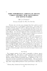
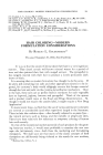
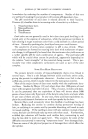
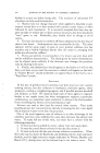
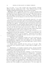
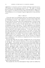
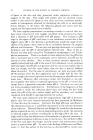
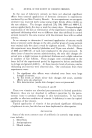
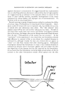
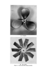
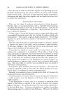
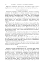
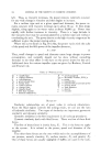
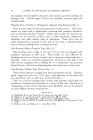
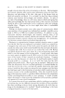
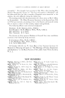
(a) Propeller. "•ib) Fan turbine. Figure &--Typical axial flow mixing impellers.

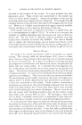
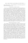
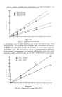
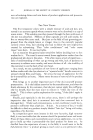
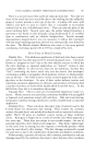
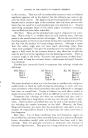
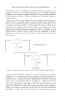
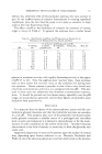
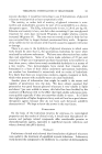
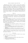
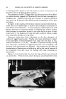
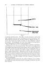
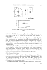
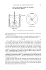
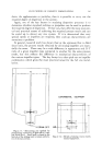
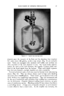
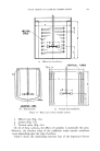
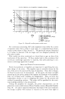
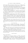
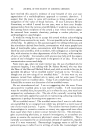
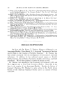
FLUID MIXING OF COSMETIC FORMULATIONS 339 FLUID FLOW PATTERN- PROPELLER POSITIONED ON CENTER WITH BAFFLES rl SIDE VIEW BAFFLES BOTTOM VIEW Figure 7.--Axial flow pattern, on center with baffles. The flow produced by the mixing impeller, •, is measured as pounds of fluid flowing per hour. Studies on the pumping capacity of mixing impellets show that for a geometric series of impellets, the flow is given by the proportionality, ,• o: ND a (2) The impeller head is an important consideration, since it is related to the velocity head leaving the tips of the impeller blade. This velocity stream leaving the impeller comes in contact with slower moving fluid in the tank (Fig. 9) and sets up a fluid shear at the boundary of these streams. This sets up turbulence at the boundary of the stream. There is turbu- lence in the stream from the impeller if the Reynolds Number is high enough, so we have an over-all fluid shear throughout the entire mixing tank. The impeller head is related to the fluid shear, which in turn is a means of providing turbulence in the system. Much research work is being done to learn more about fluid shear and turbulence in the mixing system. At the present time, we use the over-all term impeller head to give a qualitative representation to the level of fluid shear in the system. There are times when we are interested in the absolute value of the impeller head, but most often we are interested in the ratio of fluid flow to fluid shear. If we consider a mixing tank and consider that the impeller size to tank size ratio is given by the ratio of D/T, we find that the flow to fluid shear ratio is related to the D/T ratio.
Purchased for the exclusive use of nofirst nolast (unknown)
From: SCC Media Library & Resource Center (library.scconline.org)