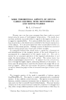
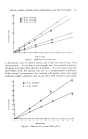
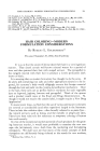
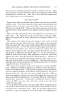
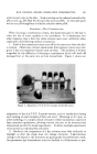
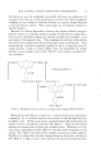
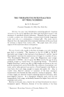
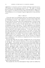
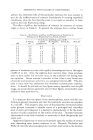
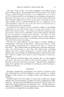
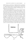
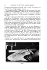
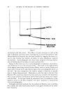
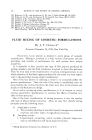
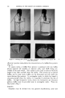
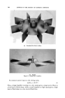
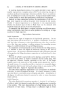
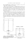
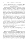
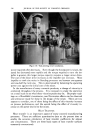
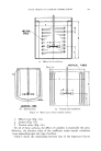
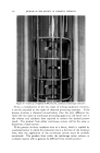
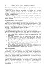
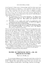
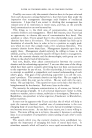
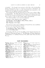
FLUID MIXING OF COSMETIC FORMULATIONS 349 HELICAL• COILS d (a) Helical coil installation. VERTICAL TUBES S½• .,.- • JACKETED TANK (b) Jacketed tank. (c) Vertical tube installation. Figure 15.--Basic types of heat transfer surfaces. 1. Helical coils (Fig. 15a). 2. Jackets (Fig. 15b). ß 3. Vertical tubes (Fig. 15c). On all of these surfaces, the effect of variables is essentially the same. However, the absolute value of the coefficient under certain conditions varies depending upon the type of surface. Table 1 shows the relationship between four of the important factors

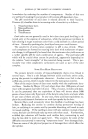
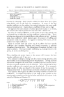
350 JOURNAL OF THE SOCIETY OF COSMETIC CHEMISTS TABLE l--RELATIVE HEAT TI•ANSFEI• COEFFICIENT COMPARED WITH HELICAL COILS Factor Helical Coils Vertical Tubes Jackets Mixer side coefficient 1,0 1.0 0 65 Area available 1.0 0.5 0, 5 Inside film (cooling water) 1.0 0.1 0.5 Inside film (steam) 1.0 1.0 1 0 involved in choosing a heat transfer surface for these three basic types, using helical coils as the basis for comparison. In terms of the heat transfer coefficient on the surface, the vertical tube gives the same coeffi- cient as the helical coil. Jackets have a coefficient 65 per cent as high. In regard to the total amount of surface practical to place in a system, the vertical tube and the jacket have less area than a helical coil. In terms of cooling coefficients on the inside of the tubes, helical coils are formed from a single tube, and the coefficient is relatively high. Verti- cal tubes are often set up for parallel flow so the cofficient is low. Jacketed tanks have coefficients which depend upon the amount of baffling and circulation inside the jacket. In regard to heating with steam, all the surfaces have high coefficients. There is actually little the mixer can do to affect the heat transfer coefficient once complete blending and forced convection is achieved throughout the entire tank. The temperature throughout the fluid in the tank is uniform. The heat transfer coefficient, h0, is proportional to the power, P, to the one-fifth power. ho • p1/• (4) Thus, doubling the power input to the system will increase the heat transfer coefficient only 15 per cent. It is common to design a mixing tank for a basic mixing operation, with heat transfer as an accompanying part of the operation. As long as forced convection throughout the entire tank is satisfied, the heat transfer charac- teristics are usually as good as can be obtained. After calculating the heat transfer coefficient, the required area can be obtained. If an extremely large number of tubes are placed in the system, it may be necessary to increase power level to insure forced convection around all tube surfaces. The equation below gives the effect of mixing variables on helical coil coefficients. A complete description of the range of the variables in this equation plus comparison with vertical tubes and helical coils is given in the article by Oldshue and Gretton (2). where h = film heat transfer coefficient o = density of fluid k -- thermal conductivity u = viscosity at tank temperature d = tube diameter Ce = specific heat D = impeller diameter T = tank diameter
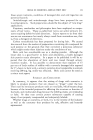
Purchased for the exclusive use of nofirst nolast (unknown)
From: SCC Media Library & Resource Center (library.scconline.org)