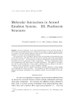
J. ,b'oc. Cosmetic Chemisls, 20, 525-537 (Aug. 19, 1969) Identification And Ouantitative Determination Of Propellants In Aerosols P. G. BOURNE, B.A., and W. R. MURPHY, B.S.* Presented September 1•2, 1968, Seminar, Boston, Mass. Synopsis--q'his paper describes a gas chromatographic method for analyzing propellants in aerosols. The method utilizes a can-piercing device attached to a liquid sampler which allows injection of sample directly from the aerosol can into the gas chromatograph. Chro- matographic conditions, standards preparation, calibration, identification of unknown peaks, and calculation of results are also discussed. INTRODUCTION Published methods for the quantitative determination of pro- pellants in aerosols have used gas chromatography with a variety of sampling techniques including: 1. direct injection into an evacuated gas sampling valve, 2. syringe injection of a chilled sample, 3. injection of a sample diluted with a less volatile internal standard, and 4. introduction into a large previously evacuated container. Most of these techniques require steps which consume time and tend to add additional error to the determinations. Direct injection into an * Gillette Toiletries Company, Gillette Park, South Boston, Mass. 02106. 525

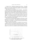
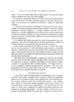
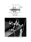
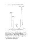
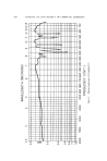
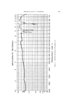
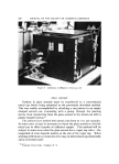
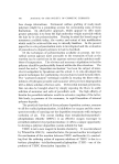
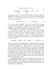
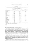
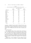
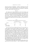
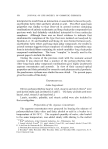
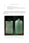
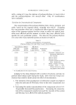
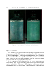
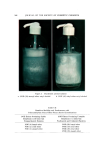
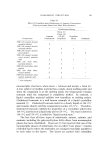
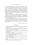
526 JOURNAL OF THE SOCIETY OF COSMETIC CHEMISTS evacuated gas sampling valve works well on certain sample types. There is the disadvantage, nevertheless, of condensation in the gas valve which results in sample trailing into the column, thus yielding several undesirable effects. The use of a liquid sampling valve, which can be attached directly to a metal aerosol can with a conventional can-piercing device, completely eliminates the shortcomings previously mentioned and yields the added advantage of excellent reproducibility. Retention times based on known samples are usually sufficient for the identification of propellants. However, in the analysis of unknown samples, an occasional unidentifiable peak may appear on the chromato- gram or a given peak may be suspected of containing more than one component. Infrared spectra can be obtained by using an adequate sample size and collecting the column effluent in a conventional 10-cm gas cell. EXPERIMENTAL Sampling Valve And Can-Piercing Device The liquid sampling valve* was equipped with a 1-tzl sampling stem. The valve and a schematic diagram are shown in Fig. 1. The Micro-Tek valve was connected to the chromatograph by splic- ing into the carrier gas line just prior to the injection port. A metal brace was bolted to the chromatograph to hold the valve rigidly in place. This setup does not prevent normal usage of the injection ports. The can-piercing devices t were attached to the Micro-Tek valve with a 6-in. section of }•-in. i.d. stainless steel tubing. This can be readily bent to facilitate sampling from the liquid phase of the aerosol and is sturdy enough to support the weight of aerosols up to 7 oz. The com- plete setup is shown in Fig. 2. Chromatographic Conditions The instrument used was an F and M 5750 research gas chromato- graph equipped with dual thermal conductivity detectors and Moseley Recorder. * Series 6000, Micro-Tek Instrument Co., Inc., 7330 Florida Blvd., P.O. Box 15409, Baton Rouge, La. 70815 • Obtained from Builders Sheet Metal Works, 108 Wooster St., New York, N.Y.
Purchased for the exclusive use of nofirst nolast (unknown)
From: SCC Media Library & Resource Center (library.scconline.org)