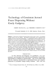
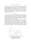
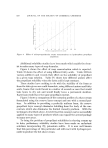
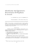
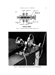
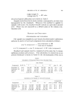
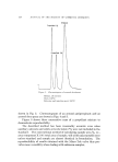
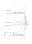
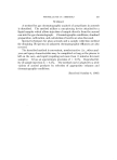
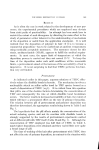
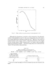
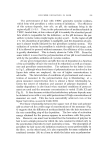
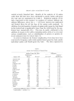
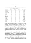
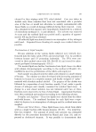
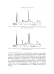
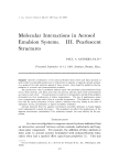
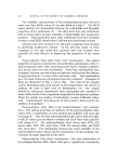
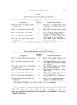
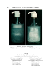
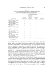
FIG. PROPELLANTS IN AEROSOLS TO COLUMN SAMPLE OUT MOUNTING NUT KNURLED STEM RETAINER NUT 527 STATIC O-RING SAMPLING STEM SEAL t • ENCAPSULATED TEFLON SEAL CARRIER 6AS SAMPLE IN MANUAL MODEL Figure 1. Schematic diagram of liquid sampling valve Figure 2. Liquid sampling valve attached to gas chromatograph

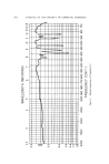
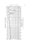
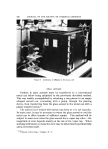
528 JOURNAL OF THE SOCIETY OF COSMETIC CHEMISTS Operating temperatures were: injection port, 200øC column oven, isothermal operation, 110 and 130 øC and detector, 200 øC. A 6-foot Par II* column was connected in series with one 8 feet long of Carbowax 20Mr, 10% on 80-100 mesh acid-washed chromosorb. Both columns were 1/• in. in diameter stainless steel. Detector current was 170 mA and helium flow was 20 ml/min. An Infotronics CRS-11HSI: digital integrator with Model B-5 automatic baseline drift corrector was also used. Preparation Of Standards For quality control testing, or in those cases where the formulation of the aerosol is known, a single standard targeted on the formulation is adequate. The authors' experience indicates that standards must con- tain the same solvent system as samples to be tested, but need not con- tain solids unless they exceed 7%. Standards were prepared as follows (all weights to the nearest 0.1 g): The can and valve were weighed, then the nonpropellant ingredients were weighed individually into the can, and the valve was crimped to the can. The can should not be evacuated. The propellant ingredients were next added in order of ascending vapor pressures with a pressure buret using nitrogen gas at least 10 psig above the vapor pressure of the most volatile component to avoid loss of any ingredient from the can. The weight per cent of each propelilant was calculated. Calibration (Calculation Of Response Factors) The chromatograph was set up with the Micro-Tek sampler attached as previously described. The piercer was attached to the can and [as- tened to the liquid sampler. The position of the can should be adjusted to insure liquid phase of the standard over the piercer orifice. Three consecutive runs were completed on each standard and the area per cents of each propellant were calculated. (Attenuation is not essential since the Infotronics integrator is connected directly to the detectors.) The Response Factor (RF) for each propellant was calculated as follows: * Porous polymer manufactured by Hewlett-Packard, Avondale, Pa. • Carbowax column manufactured by Hewlett-Packard, Avondale, Pa. • Digital integrator manufactured by Infotronics Corporation, Houston, Texas.
Purchased for the exclusive use of nofirst nolast (unknown)
From: SCC Media Library & Resource Center (library.scconline.org)