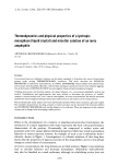
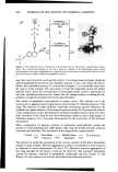
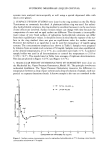
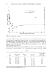
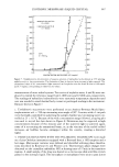
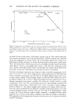
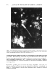
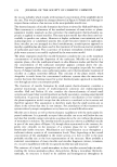
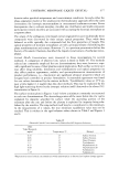
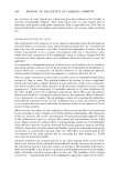
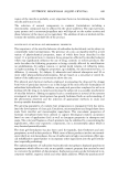
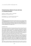
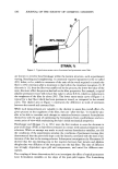
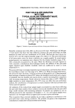
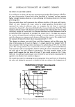
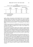
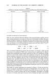
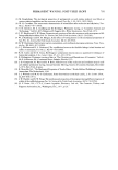
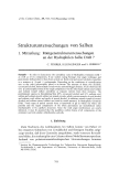
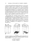
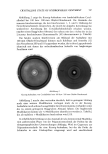
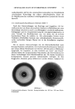
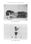
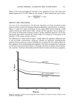
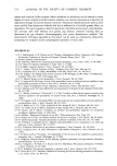
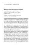
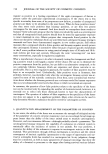
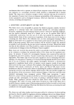
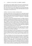
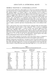
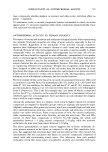
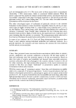
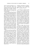
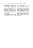
CHARACTERIZING ALUMINUM SKIN INTERACTION 719 Figure 1. Electronic instrumentation. Figure 2. Membrane diffusion cells.

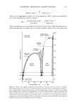
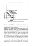
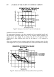
720 JOURNAL OF THE SOCIETY OF COSMETIC CHEMISTS megaohms 0.001/.tF to 100/.tF and were adjusted to balance the respective resistance and capacitance properties of the system. The resultant balance was monitored on an oscilloscope. The oscilloscope monitored 1.0V Vdc and the horizontal and vertical amplifiers were matched. Diffusion cells. Glass diffusion cells (Figure 2) were made from 15mm i.d. vacumm-tight, O-ring, glass joints. The joints were cut and sealed to hold 5.0ml and 3.0mi. Each cell had a side arm 5 cm long by 3 mm i.d. for the insertion of the stainless steel electrode. The cells were joined by a standard glass clamp and a type "M" O-ring. METHOD Differences in impedance between tissue samples, even from the same animal, have been noted by several workers (14,21-23). For this reason, the impedance of each section of excised membrane was measured prior to treatment. The measurement served to verify the integrity of the membrane as well as to establish a control value. The following regimen was used for each piece of excised stratum c0rneum and each solution of interest. A 2.5-cm square section of tissue was cut from a larger sheet of membrane and placed on a 4-cm square piece of fiberglass screening the tissue was then covered by another piece of screening. The sandwiched membrane was placed in an uncovered weighing dish and dessicated over anhydrous calcium sulfate (10-20 mesh) for 24 hr to stabilize the tissue. The weighing dish was then removed and placed over water in another covered dessicator for 17 hr to hydrate the tissue to a standard value. The skin was then removed from the screening and placed between the diffusion cells. The O-rings were employed to tension mount the tissue in place. Standard glass joint clamps were used to hold the chambers together. The appropriate control solutions were then added to both sides of the cells. The electrodes were inserted into the appropriate sidearm and the system was placed in the 35øC waterbath. Impedance was then measured. An X-vs.-Y mode was used to compare and match the phase and magnitude of voltage across the membrane with those of the decade boxes. Balance was assumed when a 45 ø angle was observed in relation to the X-Y axis. From the decade units, values representing those of the membrane were obtained and the related impedance value, Z, in ohms, was calculated, using the formula: 1 '¾/2 z = (R2+ where R and C are the values observed on the resistance and capacitance decade boxes respectively, and f is the frequency of the alternating current. Thus, the ac conductance is the reciprocal of the calculated impedance, Z. After the impedance had stabilized, the rinse solution was removed and the chambers rinsed six times with additional rinse solution. The test solution was then added to the 5.0-ml side of the chamber and the rinse solution added to the 3.0-ml side. A teflon stirring bar (3 X 9 mm) was added to the receptor side (control side) to disperse any ions which might have diffused through the membrane. The cells were reintroduced to the waterbath and placed on a support over a microsubmersible magnetic stirrer. The change in impedance, AZ, was monitored as a function of time until the impedance again stabilized. All test solutions were monitored for 5-6 hr. Twenty-four hour measurements showed that no additional major change in impedance had taken place. To compare the
Purchased for the exclusive use of nofirst nolast (unknown)
From: SCC Media Library & Resource Center (library.scconline.org)