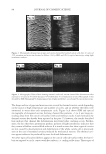
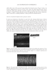
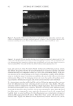
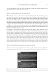
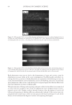
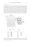
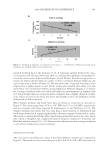
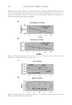
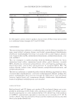
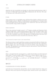
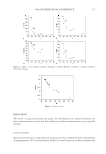
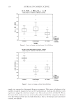
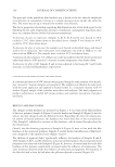
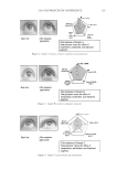
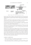
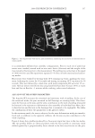
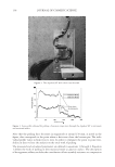
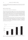
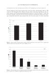
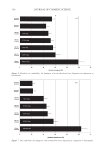
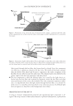
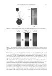
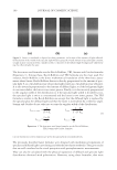
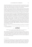
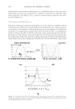
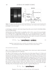
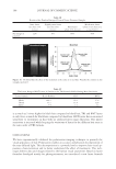
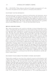
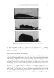
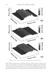
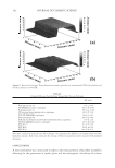
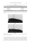
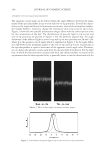
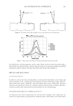
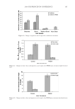
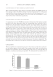
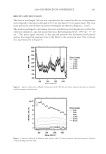
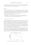
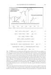
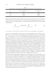
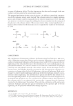
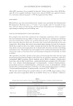
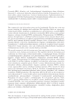
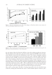
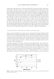
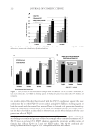
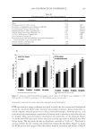
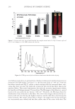
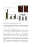
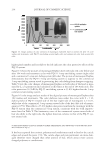
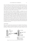
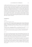
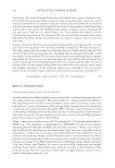
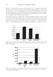
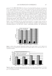
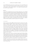
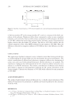
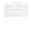
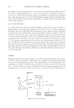
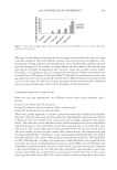
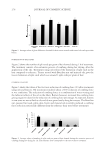
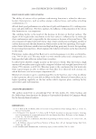
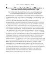
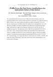
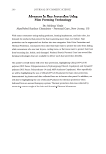
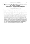
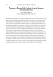
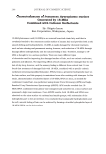
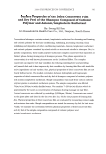
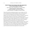
JOURNAL OF COSMETIC SCIENCE 88 The shape and size of gaps and microcavities created by thermal stresses varied depending on the source of high temperature and number of cycles, and on whether the fi bers were immersed in water after each temperature cycle. Figure 3a,b shows SEM and optical micrographs of elongated cavities forming channel-like patterns ~3 to 4 um long pro- truding away from the cuticle cell surface with and without cracks. Crack formation by thermal stresses has already been reported in the past (7), however, the results described here indicate that channel like deformations may form before cracking occurs. Further- more, the fact that these protrusions produce patterns of light interference indicates that they consist of hollow cavities fi lled with air. It is worth to note that these types of cavities are not caused by decementation and deformation of the whole cuticle cell as previously seen in the case of extended cavities produced by mechanical stresses. The thermal cavi- ties appear rather to be produced by more localized deformations. Yet other types of localized defects appear at the cuticle cells sub-surface when the hair fi - bers are exposed to cyclic contact with hot surfaces, i.e. curling or fl at irons. These types of Figure 2. Micrographs showing typical gaps and cavities formed by buckled cuticle cells after 20 cycles of 15% extension and retraction obtained as follows: (2a) by SEM, and (2b) by optical microscopy using light interference analysis. Figure 3. Micrographs (250×) of hair showing thermal cracks and narrow channel-like deformations after exposure to 15 cycles of 30-s blow-drying at 75°C followed by 30 s of immersion in water. Micrograph 3a was obtained by SEM. Micrograph 3b, displaying patterns of light interference, was obtained by optical microscopy.

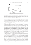
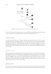
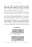
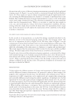
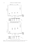
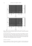
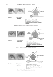
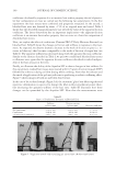
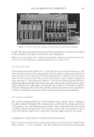
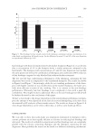
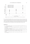
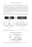
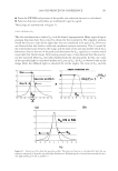
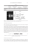
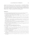
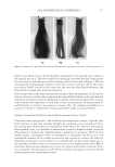
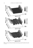
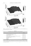
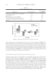
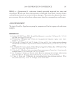
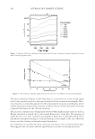
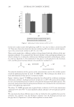
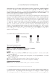
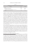
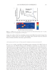
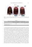
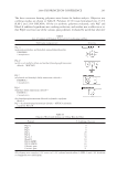
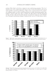
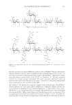
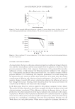
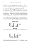
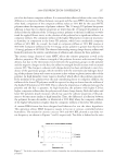
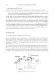
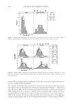
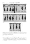
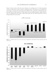
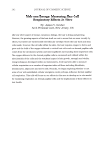
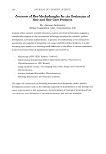
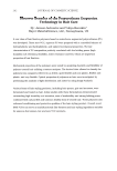
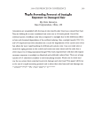
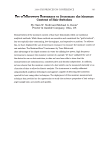
2008 TRI/PRINCETON CONFERENCE 89 defects approximately 1–3 μm in diameter form cavities fi lled with air as evidenced by their associated punctual bright colored spots due to light interference (see Figure 4a,b,c). An inspection of the SEM micrographs and the light interference patterns shown in Fig- ures 4a and 4b indicates that these types of defects are of two types, namely, (i) cavities forming bulges and blisters protruding away from the surface, and (ii) cavities buried deep beneath the surface with no bulging. The formation of such disruptions in the continuity of the cuticle cell certainly constitutes a loss in the cross-linking density of the protein structure due to a rapid expansion of water within the cuticle cell (see Figure 4c). GAPS AND CAVITIES FORMED BY SOLVENT EXTRACTION The immersion of hair fi bers in solvents increased substantially the average number of micro-cavities (see Figure 1, line c) although, not all cuticle cells were affected by the immersion and only a few cuticle cells underwent cavity formation. Furthermore, it was observed that immersion in IPA always led to higher increments in the number of micro- cavity and gap formation than did fi ber immersion in hexane. Increments in the number of gaps and cavities appearing in regions closer to the root after solvent immersion were low, while in regions away from the root, the increments were quite large. These observa- tions suggest that increments in the number of micro-cavity and gap formation observed after solvent immersion are related to damage that has been done to hair prior to solvent immersion. If this were not the case solvent immersion would produce equal increments of defects all along the fi ber from root to tip. However, before adopting this hypothesis as conclusive, we should analyze other alterna- tive explanations. One possible hypothesis is that gaps and cavities formed after solvent immersion is due to solvent swelling. For instance, it is known that IPA has the ability to swell the hair fi ber. However, hexane does not swell the keratin fi ber and yet it causes gap Figure 4. Micrographs (400×) of typical bulges and blisters formed in hair fi bers after exposure to fi ve cycles of 30 s in contact with a hot iron surface at 120°C followed by 30-s immersion in water. Figure 4a was ob- tained by SEM. Figure 4b, showing patterns of light interference, was obtained by optical microscopy. Figure 4c is a schematic representation of loss of continuity within the cuticle cell, leading to cavity formation by rapid water evaporation.
Purchased for the exclusive use of nofirst nolast (unknown)
From: SCC Media Library & Resource Center (library.scconline.org)