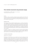
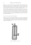
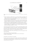
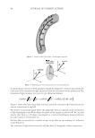
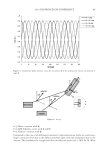
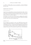
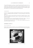
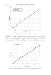
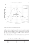
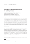
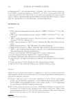
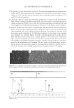
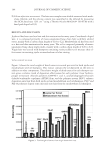
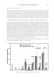
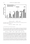
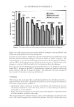
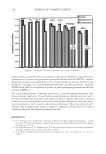
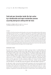
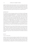
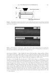
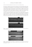
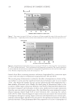
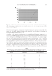
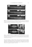
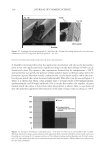
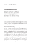
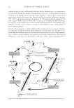
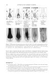
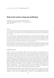
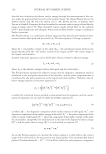
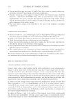
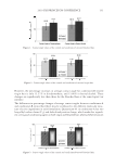
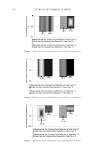
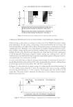
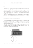
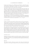
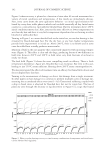
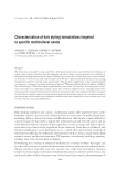
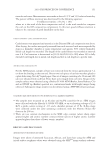
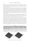
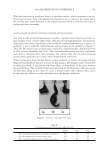
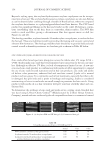
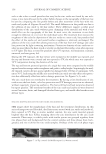
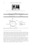
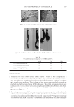
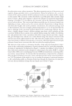
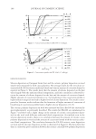
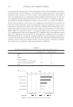
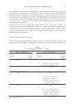
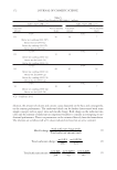
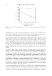
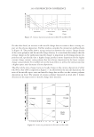
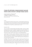
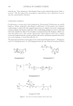
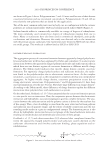
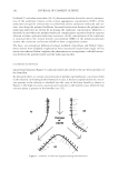
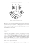
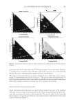
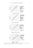
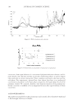
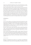
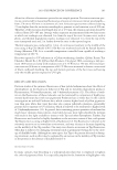
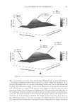
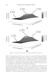
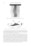
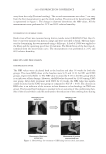
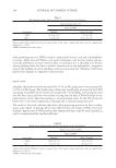
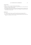
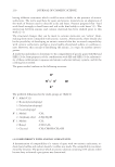
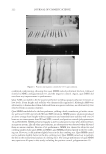
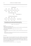
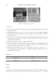
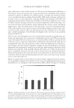
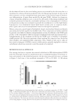
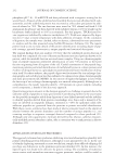
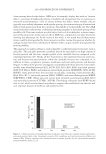
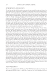
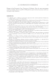
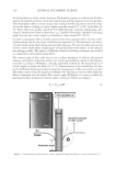
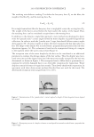
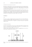
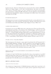
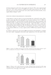
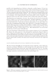
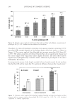
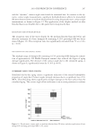
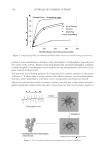
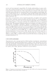
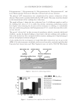
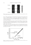
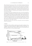
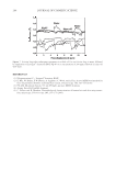
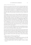
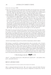
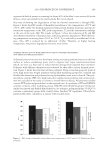
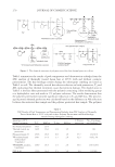
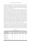
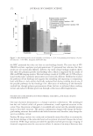
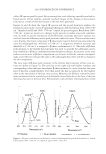
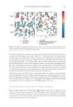
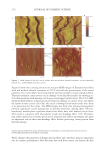
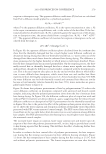
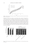
JOURNAL OF COSMETIC SCIENCE 88 A simultaneous rotation of both polarizers (Angle ϕ compared to vertical axis) allows the collection of the transmitted light intensity versus the orientation of the polarizer ϕ. The transmitted light intensity I is given by the following formula: ^ ` R R 1 1 1 1 1 cos 1 cos cos 4 4 2 2 _ IT T I ª º Figure 5 shows the transmitted light intensity versus the orientation ϕ of the polarizer for various orientations of angle θ. We observe a sinusoidal signal where the amplitude does not depend on the orientation of the birefringence axis θ but where the phase of the signal is related to θ. We can also observe that there is a 90 degree uncertainty as a vertical birefringent material delivers the same signal as a horizontal one. For hair fi ber, we proceed to a similar set-up, except that we are working in a refl ection mode (Figure 6). The intensity of light backscattered by the hair fi ber is composed of three components: Figure 3. Simple model: Hair fi ber = birefringent material. Figure 4. Birefringence axis measurement set-up (transmission).

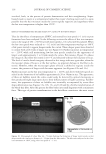
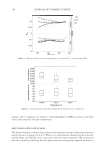
2010 TRI/PRINCETON CONFERENCE 89 I • s (Shine, constant with ϕ) I • c (ϕ,θ) (Chroma, varies with ϕ and θ) I • d (Diffuse, constant with ϕ) Compared to the case of a birefringent material in the transmission mode, we now have a larger continuous level due to the diffuse and shine light, with the modulation due to the chroma. The retardance for a single hair fi ber in refl ection mode is R = 2π/λ Δn 2d. With Figure 6. Set-up. Figure 5. Transmitted light intensity versus the orientation ϕ of the polarizer for various orientations of angle θ.
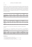
Purchased for the exclusive use of nofirst nolast (unknown)
From: SCC Media Library & Resource Center (library.scconline.org)