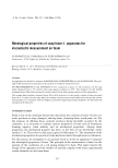
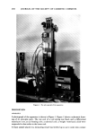
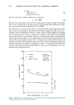
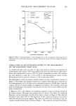
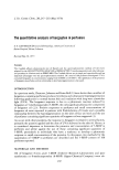
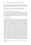
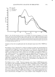
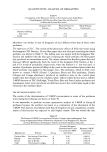
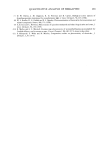
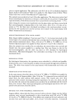
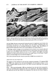
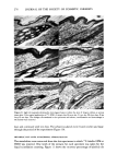
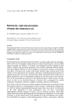
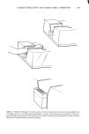
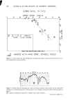
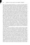
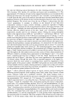
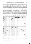
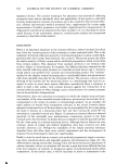
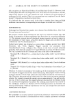
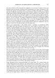
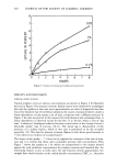
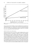
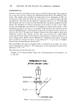
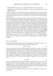
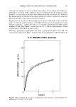
238 JOURNAL OF THE SOCIETY OF COSMETIC CHEMISTS Figure 1. The photograph of the apparatus DESCRIPTION APPARATUS A photograph of the apparatus is shown in Figure 1. Figure 2 shows a schematic draw- ing of its principle parts. The top end of a coil spring was fixed, and a differential transducer core, an air bearing core, a solenoid core, a weight vessel and a disk were suspended in that order to the lower end. A foam sample placed in a measuring vessel was leveled up so as to come into contact

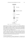
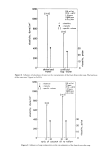
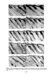
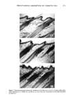
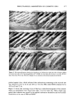
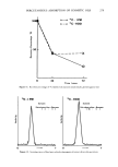
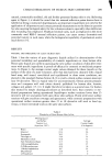
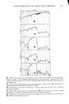
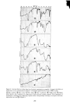
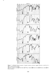
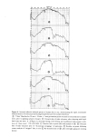
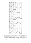
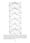
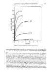
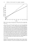
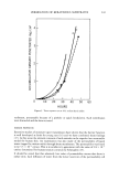
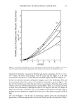
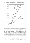
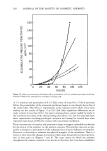
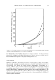
VISCOELASTIC MEASUREMENT ON FOAM 239 Coil spring Differential transducer Air bearing Solenoid Weight •Disk Foc•m Figure 2. Schematic drawings of principal parts of the apparatus with the disk (12 mm in diameter, 1 mm in thickness). A free oscillation ofagiven am- plitude and frequency was applied to the sample with the aid of the solenoid. The os- cillation damped by the sample was changed into an electrical signal. The signal taken from the differential transducer was passed to a transducer meter and, after amplifica- tion and filtration, was recorded by a recorder. At the same time, a period of the os- cillation was measured by a digital period meter. The air bearing was used to prevent the eccentric motion of the oscillating system's axis. An example of the oscillation damped by foam is shown in Figure 3 together with a control-free oscillation. The top pattern of the figure is without foam and the bottom pattern is with foam. The decrement of the oscillation was apparent with foam, however the oscillation was damped slightly even without foam. The decrement of the free oscillation, possibly caused by the viscosity of air, was taken into account when cal- culating the true decrement of the oscillation damped by foam. THE DEVICE FOR SAMPLE PREPARATION A commercial foam-generator (John Oster Manufacturing Co., Latherservice Ma- chine © ) was adapted by improving the following defects. First, we were unable to main-
Purchased for the exclusive use of nofirst nolast (unknown)
From: SCC Media Library & Resource Center (library.scconline.org)