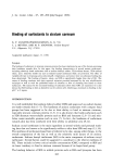
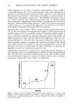
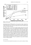
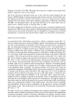
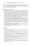
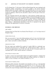
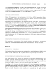
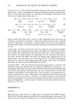
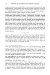
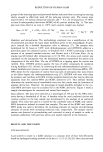
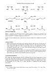
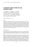
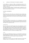
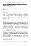
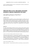
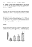
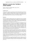
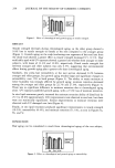
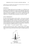
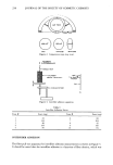
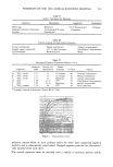
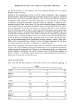
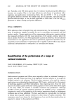
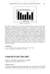
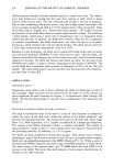
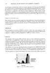
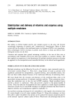
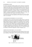
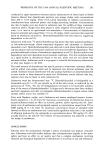
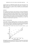
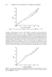
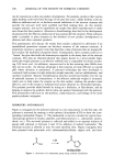
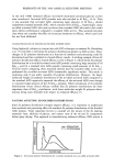
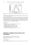
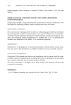
PREPRINTS OF THE 1996 ANNUAL SCIENTIFIC MEETING 257 method that also accomplishes radial compression in principle during the traversal of a hair tress through a ring of a given diameter. EXPERIMENTAL Ten tresses of European dark brown hair, each weighing 13 g (--9000 fibers) were prepared and cleaned by washing with a solution of 10% sodium lauryl sulfate, dried, and conditioned at 65% RH and 21øC. After the radial compressibility measurements on the untreated tresses, they were given different treatments to impart different levels of body. The tresses were numbered 1-10 in the order of increasing body. After measurement of radial compressibility, the tip end of the tresses were packed in a cylinder and cut to make fiber adhesion measurements by the pull-out method. RADIAL COMPRESSIBILITY The radial compressibility apparatus is shown in Figure 1. The top view of the split rings used in tress compression are shown in Figure 2. Even though the method is referred to as radial compressibility, it should be realized that the tress is compressed to an elliptical rather than a circular cross-section. In a typical experiment the tress was combed and fluffed and mounted in the compressibility apparatus. Energy for compres- sion (E•) between fixed initial and final tress dimensions was measured. After releasing, a second measurement of compression energy (E2) was made without disturbing the tress. From these data the following quantities were calculated: AE 2 = 100 (E2,• - E2,untr)/E2,untr and FAI = 100 (El,tr -- E2,tr)/El,tr It should be mentioned that FAI is related to interfiber adhesion. High interfiber adhesion will lead to lower compression energies in the second compression, as compared to that of the first, because the tress does not recover fully to its original dimension (E 2 El). _ • Horseshoe INSTR• CROSSHEAD Figure 1. Radial compressibility apparatus.

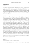
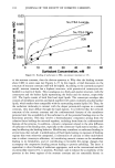
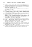
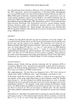
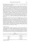
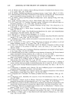
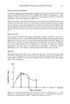
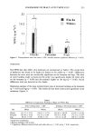
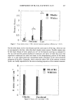
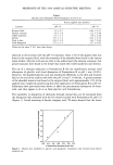
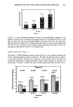
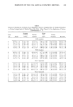
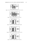
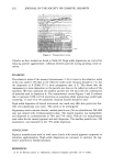
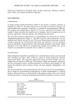
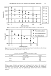
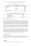
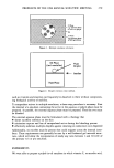
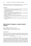
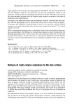
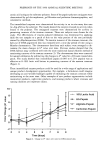
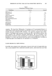
258 JOURNAL OF THE SOCIETY OF COSMETIC CHEMISTS I•ihol 1.5 mm (CHO) •0 mm (CHDI Figure 2. Compression rings (top view). RECORDING ELECTROBALANCE ,,-'-- SINGLE HAIR (40mm ß I•mm ChQ ! II I I Figure 3. Interfiber adhesion apparatus. Table I Interfiber Adhesion Forces Tress # Force (mg) Tress # Force (mg) 1 64 6 68 2 144 7 104 3 86 8 42 4 194 9 149 5 85 10 84 INTERFIBER ADHESION The fiber pull-out apparatus for interfiber adhesion measurements is shown in Figure 3. It should be noted that the interfiber adhesion is a function of fiber density, which was
Purchased for the exclusive use of nofirst nolast (unknown)
From: SCC Media Library & Resource Center (library.scconline.org)