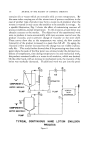
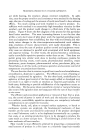
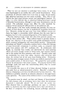
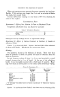
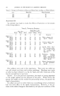
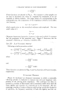
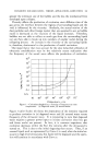
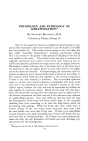
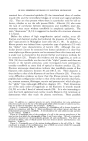
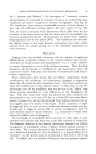
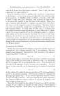
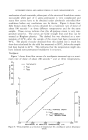
PROCESSING PRODUCTS IN VOTATOR APPARATUS 511 known to processing, their existence and specific methods of us•e are at times taken for granted. There are few operations of any kind in which, at some point or another, heat energy must not be transferred into o.r out of a voluminous amount of materials to produce the desired product or effect. Therefore, the following will deal not so much with why heat transfer is necessary, but rather with possibilities of utilizing it more efficienfly and more economically. This will be done by first describing the apparatus and then explaining how and why it performs to further clarify how the time- temperature-mechanical work relationship is controlled. Figure 1 shows a cross section of'the Votator scraped surface heat transfer apparatus consisting of an insulated jacket surrounding a heat transfer tube. The ends of this tube are closed with heads that .contain bearings for a shaft mounted concentrically within the tube. This mutator shaft, which rotates and carries scraper blades, is the essential device for: 1. Effecting rapid heat transfer. 2. Preventing localized overheating or cooling. 3. Furnishing the necessary agitation or work to emulsify, homogenize, plasticize or make finer dispersion of the ingredients fed to the unit. The diameter of the shaft is normally three-fourths of the internal diameter of the tube, thus providing a relatively small annular space for product passage. Nevertheless, if more or less process time is required, this annulus may be increased or decreased by decreasing or increasing the shaft diameter. The heads containing the bearings in which the shaft turns are provided with an inlet and outlet for the product. Where multiple injection of ingredients is necessary, the inlet head is equipped with the appropriate number of inlet ports. The assembly just described is a complete cylinder assembly. One or more of these assemblies are either direct driven or mounted on a cabinet which houses the electric motor and starting equipment for driving the shafts. The rotational speed of the shaft in the latter case is fixed by the appropriate choice of pulleys or sprockets between the shaft and the electric motor. On those occasions where shaft r.p.m. must be varied, more work and mixing for 6he product and less for another, a variable drive is furnished. The ingredients are fed from the preparation vessels to an appropriately chosen pump which con- tinuously moves the material to be processed from inlet through the annular space to the outlet. The heat transfer medium, in the required amount, enters and leaves the insulated jacket through provided openings. The annular space in the jacket is designed to enable the medium to pass through it in varying but sufficient quantity and at maximum velocity to create turbulence and a minimum pressure drop. The transfer medium can be water, steam, ammonia, Freon, Dowtherm, or brine. The transfer tube separates the product and the medium and can be constructed of

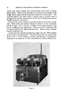
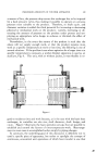
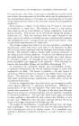
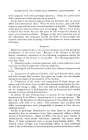
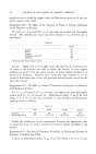
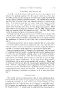
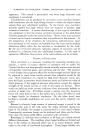
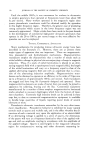
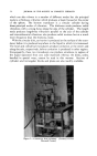
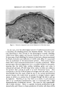
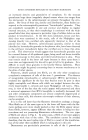
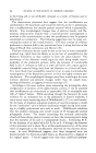
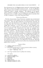
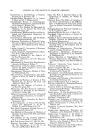
512 JOURNAL OF THE SOCIETY OF COSMETIC CHEMISTS carbon steel, nickel, stainless steel, chrome plated carbon steel or chrome plated nickel. Choice of the materials of construction and design of the sC•al•er blades is governed by the physical properties of the product. The rotational speed of the shaft, which is usually made of stainless steel, is determined by the flow characteristics of the material being processed and the effect desired on the product. The size of the units is based on the internal diameter of the heat transfer tube. Units used in the cosmetic industry are either 4 or 6 in. in diameter and 48 in. long. The 4- and 6-in. cylinders contain approximately 4 and 6 sq. ft. of effective area, respectively. Units up to 24 in. in diameter, 120 in. long are used for very large production rates. Figure 2 shows a typical sanitary production unit. At this point the cosmetic manufacturer might well ask, "Why should I be interested in this apparatus ?" The answer lies in the very nature of the process used to make cosmetics namely, emulsification, crystallization, texturization and gelation to obtain controlled and uniform fluidity, con- :. : ...•:• ..... •:"•:•* ' • -: *,.. '.•*' ..... •:e .... •.•X'.'• ",.:. ,•.• ... : :. ß, .... -t .:•-z - • .' ß .. .,•..:..,. 'L.. ::.? .. ':'.: i/. *:.. : • :'..: ...... , ., :: . ,. .•. .... . .: Figure 2
Purchased for the exclusive use of nofirst nolast (unknown)
From: SCC Media Library & Resource Center (library.scconline.org)