VISUALIZATION OF SKIN BARRIER PERTURBATION 267 Sulforhodamine B (SRB), a hydrophilic fluorescent probe, was obtained from Molecular Probes (Eugene, OR). Sodium cocoyl isethionate (SCI) from BASF was provided to us by Unilever (Edgewater, NJ). All these chemicals were used as received. Water was filtered using a Millipore Academic water filter (Bedford, MA). Phosphate-buffered saline (PBS) was prepared using PBS tablets from Sigma Chemicals and Millipore filtered water, such that a phosphate concentration of 0.01 M along with a NaCl concentration of 0.137 M were obtained at a pH of 7 .2 PREPARATION OF THE SOLUTIONS For the visualization of SRB in p-FTS, a solution of 0.05 mg/ml of SRB in PBS was prepared. The following aqueous solutions of surfactants, a humectant, and a surfactant+humectant mixture that contacted p-FTS were prepared: (i) a harsh surfactant solution-SOS (1 wt%) (ii) a harsh surfactant+humectant solution-SOS (1 wt%) + glycerol (10 wt%) (iii) a mild surfactant solution-SCI (1 wt%) 5 (iv) a control solu tion-PBS and (v) a humectant solution-glycerol (10 wt%). Note that a mild surfactant+humectant solution-SCI (1 wt%)+glycerol (10 wt%) did not induce skin morphological modifications different from those induced by solutions iv and v and, therefore, is not discussed here. PREPARATION OF THE SKIN SAMPLES Female Yorkshire pigs (40-45 kg) were purchased from local farms, and the skin (back) was harvested within one hour after sacrificing the animal. The subcutaneous fat was trimmed off using a razor blade, and the full-thickness pig skin was cut into small pieces (2 cm x 2 cm) and stored in a -80°C freezer for up to two months (2--4,34,45). IN VITRO DIFFUSION CELL SKIN EXPOSURE TO SURF ACT ANT-HUMECT ANT SYSTEMS FOLLOWED BY EXPOSURE TO SRB Prior to use in the TPM skin visualization experiments, the p-FTS sample was thawed for half an hour. The p-FTS sample was then mounted in a vertical Franz diffusion cell obtained from Permegear (Bethlehem, PA) with the SC facing the donor compartment. Both the donor and the receiver compart�ents were filled with PBS, and the p-FTS sample was left to hydrate for one hour to allow the skin initial barrier property to reach steady state. At this point, the skin electrical current across the p-FTS sample was measured at a 100 m V AC voltage (RMS) at 10 Hz, and only p-FTS samples with an initial skin current 3 µA were utilized in the permeation studies (2,45). The PBS in the donor compartment of the diffusion cell was then replaced with 1.5 ml of aqueous contacting solution i, ii, iii, or v. The aqueous solution in each donor compartment was then allowed to contact the p-FTS sample for five hours. Following this skin treatment with each aqueous contacting solution, the aqueous contacting solution was removed and 5 Note that p-FTS samples were contacted with aqueous SCI solutions at 35 ° C, while they were contacted with aqueous solutions i, ii, iv, and vat room temperature (25 ° C). This is because SCI (1 wt%) is soluble in water at 3 5 ° C, but not at 2 5 °C ( 6,45 ).

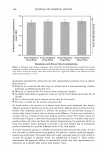
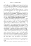
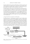
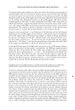
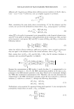
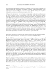
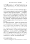
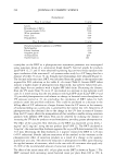
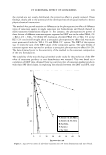
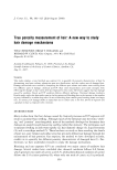
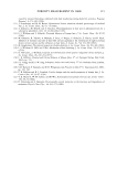
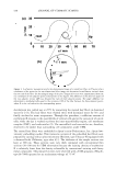
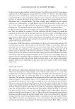
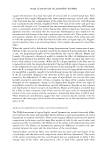
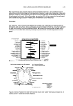
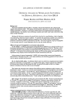
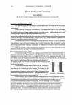
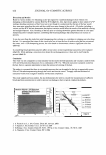
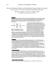
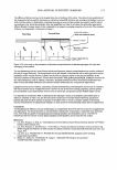
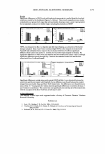
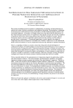
268 JOURNAL OF COSMETIC SCIENCE the donor compartment along with the p-FTS sample was rinsed four times with 2 ml of PBS to remove any trace chemical left on the skin surface and in the donor compart ment. Subsequently, each p-FTS sample was exposed to an aqueous SRB fluorescent probe solution in the diffusion cell for an additional 24 hours (20-23). Each p-FTS sample was then removed from the diffusion cell, rinsed four times with 2 ml of PBS as before, and blotted with a Kimwipe (Kimberly Clark, Roswell, GA) to ensure the removal of any excess SRB present on the skin surface. The circular area of the skin exposed to SRB was cut out with a surgical carbon steel razor blade (VWR Scientific, Media, PA), and subsequently sealed in a 2.5-mm imaging chamber (Cover well, Grace Bio-Laboratories, Bend, OR) with a coverslip (VWR Scientific) that con tacted the SC side of the p-FTS sample (20-23). A drop of PBS was added to the skin surface contacting the imaging chamber to prevent drying out of the p-FTS sample. The imaging chambers containing the p-FTS samples were imaged using the TPM appara tus, as described below. TWO-PHOTON MICROSCOPY (TPM) IMAGING OF THE SKIN SAMPLES The TPM imaging of the p-FTS samples was performed using the apparatus shown schematically in Figure 1 (20,29,30). This apparatus is based on a point-scanning approach, and has the capability for three-dimensional imaging. The incident beam is emitted by a femtosecond titanium-sapphire pulsed laser (Tsunami Spectra-Physics, Mountain View, CA) pumped by a 5W diode-pumped, solid state CW laser (Millenia V Spectra-Physics) (20,29,30). The two-photon excitation is provided at 780 nm and at a laser power of 200 mW (20). The incident beam generated by the laser is deflected by the X-Y scanner system, discussed elsewhere (30), to different angular positions, and then directed to the microscope system. The microscope system consists of a modified inverted microscope (Axiovert, lO0TV Ziess, Thornwood, NY) with an oil-immersion 40x objective lens (Zeiss F Fluar, NA .13) (30). To obtain dual-channel TPM images, Microscope System Skin Diode Laser Pumped Titanium-Sapphire X-Y "S..;...;.�"-"lscanner lane ! I I I I --------' ,---------------------------------------7 : �------� �-----� : •••·••··•• . .,,...,.,,...,,,.,..,.;,,-=:,,1 Photo Multiplier Photon 1 Tube Discriminator l I I I L ______________________________________ J Photon Detection-Conversion System Computer Figure 1. Schematic illustration of the apparatus used for the two-photon fluorescence microscopy (TPM) skin-imaging experiments (20,30).
Purchased for the exclusive use of nofirst nolast (unknown)
From: SCC Media Library & Resource Center (library.scconline.org)