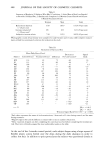
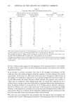
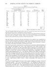
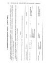
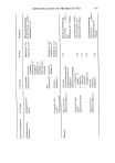
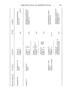
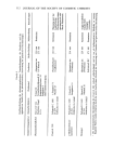
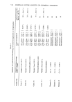
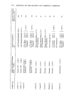
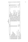
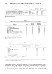
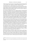
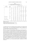
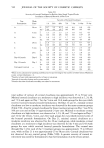
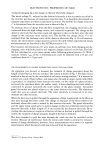
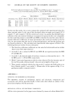
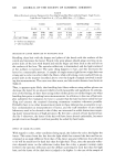
592 JOURNAL OF THE SOCIETY OF COSMETIC CHEMISTS Table I Reflection Coefficients Calculated for the cases REL Versus RER (0 equals 30 o, 0 equals 2.5 o, n equals 1.548, incident light linearly polarized Es) Intensity Ratios, REL versus RER Intensity Ratios Values REL(F)/RER(F) RER(R)/REL(R) Orientation Face Model 1 Model2 Model 1 Model 2 Experimental Model 1 Model2 Experimental REL Front 0.0703 0.0703 RER Front 0.0624 0.0624 REL Rear 0.0582 0.0624 RER Rear 0.0774 0.0703 1.127 1.127 1.205 1.330 1.127 1.109 for the rear-face peaks. Let us now compare the calculated and experimental values for these intensity ratios. In the case of the calculated values we again use & equals 30 ø, 0 equals 2.5 ø, and n equals 1.548 (for cuticle and cortex) we assume that the light losses suffered at the extra internal interfaces encountered in optical model 2 are comparable for the round trip routes in cases REL and RER so that for the rear face cases, the im- portant reflection coefficients are those pertaining to the cuticle-air interface at the far side we also assume that the rays lie in the principal plane, and that the incident rays are linearly polarized Es. The calculated and experimental values appear in Table I. The following items are worthy of note at this point. 1. The front face reflection coefficients are the same for both models and are within 10 per cent of the value observed. 2. In model 2, the rs values for REL (F) and RER (R) are equal as are those for RER (F) and REL (R). 3. In model 1, the internal angles of incidence versus •r2 on the rear face are (r - 20) for REL, and (r + 20) for RER, respectively. 4. Model 2 gives good agreement with the value observed for the intensity ratio of the rear face peaks, whereas model I does not and is high by 20 per cent. 5. These results combined with the fact that model 2 explains the EAP incline us to favor Optical model 2 over model 1. (Please refer to the caption of Fig. 12 re- garding a possible composite model.) APPENDIX I APPARATUS AND EXPERIMENTAL PROCEDURES The apparatus consists of mechanical, optical, and electronic components and accessories and will be described briefly in that order after which an outline of the procedures employed will be presented. MECHANICAL, OPTICAL, AND ELECTRONIC COMPONENTS All the curves presented in the paper were obtained by means of a Zeiss Model GP-2

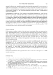
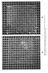
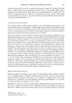
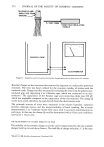
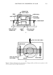
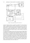
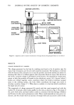
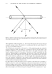
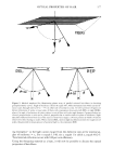
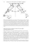
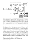
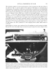
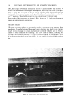
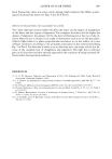
OPTICAL PROPERTIES OF HAIR 593 SM I::1 Figure 13. Electronic, mechanical, and optical components associated with mechanized goniophotometer. SM, stepping motor (Superior Electric, Model M063-FC09 with STM1800CV Translator Module) nu- merous components from PIC (Ridgefield, Conn. 06877), namely: C, various couplings SR, speed reducer (400:1) MC, magnetic clutch BG• and BG2, bevel gear boxes SI, speed increaser (1:23.3) HW, hand wheel and BC, bellows coupling øC, degree counter (Durant) P-L, P-MC, and P-SM, DC power supplies for lamp, MC and SM OSC, Wave Tek DC Square Wave Pulse Generator (Model 131A with 10 turn [potentiometer] for fine tuning) CNTR, Hewlitt-Packard Digital Electronic Counter (Model 5223L) SB, switch box for control of SM and MC GP-2, Zeiss goniophotometer F, exhaust fan L, GP lamp (6 V/5 amp.) D, UDT diffused SI photodiode detector (see text) A, UDT amplifier (see text) R, Houston series 5,000 strip chart recorder (see text). Numbers 6 and 9 alongside 2 cables refer to number of conductors in cables Goniophotometer. As received from Zeiss, the instrument had to be operated manually the detector was a selenium barrier-layer cell (photovoltaic device), and the read-out was accomplished by means of a galvanometer. A description of the Zeiss instrument was published in an article by Heinz Loof (18). A rudimentary diagram of the principal optical components is given in Fig. 6. In order to make this instrument useful in the present application, it was necessary to mechanize the drive of one of the collimators (the detector side was selected) to provide a dichroic heat filter • (placed just downstream from the condensing lens in Fig. 6) in order to reflect back to the source radiation having ?, 700 nm and thereby reduce the heating of the fibers by the incident radiation to provide polarizing discs? (Polaroid film,:l: type HN-32, cemented between plane, parallel, colorless glass discs) in fabricated metal holders capable of producing either E• or Ep in each side to provide an assortment of neutral density *Fish-Schurman Corp., 70 Portman Rd., New Rochelle, NY 10801. q-Obtained from Wakefield Precision Optics, 247 Water St., Wakefield, MA 01880. $Polaroid Corp., Cambridge, MA.
Purchased for the exclusive use of nofirst nolast (unknown)
From: SCC Media Library & Resource Center (library.scconline.org)