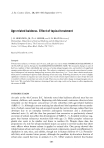
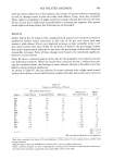
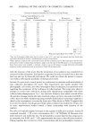
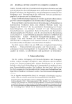
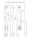
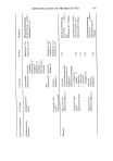
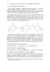
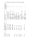
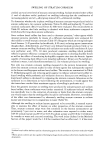
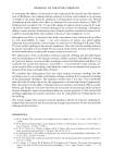
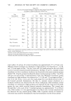
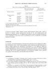
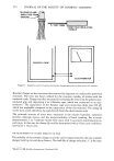
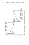
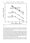
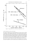
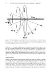
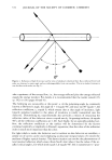
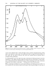
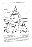
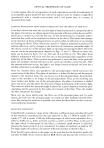
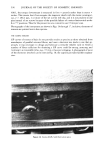
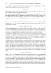
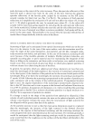
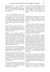
572 JOURNAL OF THE SOCIETY OF COSMETIC CHEMISTS fiber_ % Figure 1. Diffraction of light by infinite cylinder (L/D equals •). Rays of light are shown which have angles of incidence (0) of 0, 20, and 60 ø. In all cases, diffraction causes incident ray to fan out along surface which is plane normal to fiber for 0 equals 0 or along conical surface fbr • 4 = 0. To see diffracted light, eye must be in surface and looking at point of intersection of ray with fiber. by Kerker (1). It is quite probable that the mathematical methods developed to date will not be capable of predicting the light-scattering patterns to be anticipated from hair fibers which are nonconducting, nonopaque, birefringent, provided with scales, and which possess elliptical cross-sections. Even so, theory is useful here because it explains the unique type of light-scattering pattern produced by infinite cylinders, and this should be understood by anyone involved in studying the optical properties of hair fibers. NORMAL INCIDENCE Imagine a narrow beam of monochromatic parallel rays from a small laser to impinge on a straight, nonopaque, dielectric fiber with an angle of incidence of 0 ø (normal inci- dence). (Please refer to Fig. 1.) The rays will be diffracted, reflected, refracted, and scattered. The diffraction of light consists of the bending of the rays any time they en- counter the edge of an obstacle so that these rays are bent into the shadow of the obstacle. Thus, downstream from the filament, we can observe on a white card a series of spots consisting of a diffraction pattern generated by the constructive and destruc-

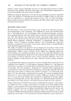
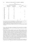
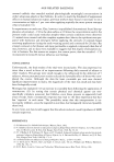
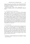
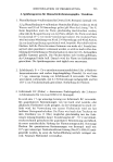
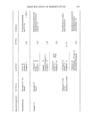
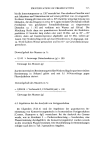
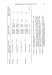
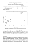
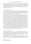
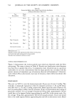
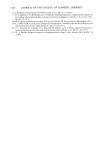
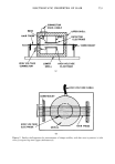
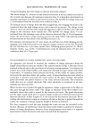
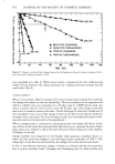
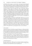
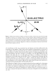
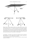
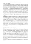
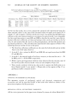
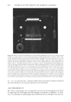
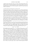
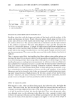
OPTICAL PROPERTIES OF HAIR 573 OIELECTRIC AIR Figure 2. Reflection and refraction of light at air-dielectric interface. Incident ray comes from lower right with angle of incidence (3. It is partially reflected at equal and opposite angle and partially transmitted into optically more dense dielectric and suffers refraction at angle r. Plane of incidence is established by incident ray and perpendicular to interface. Direction of linear polarization is specified as being parallel to plane of in- cidence (% equals • ) or perpendicular to that plane (• equals ß ) when electric vector (•) of advancing wave front vibrates in direction so specified. Magnitudes of reflection and transmission coefficients must be calcu- lated by Fresnel's equations (see text) tive interference of the rays transmitted by the filament and those diffracted by the boundaries of the filament. These spots will be displaced symmetrically on each side of a very bright central spot formed by the rays directly transmitted by the filament. At normal incidence it will be observed that all the spots lie in a plane perpendicular to the axis of the filament. By direct viewing, it is possible to see the light diffracted by the filament only when the eye is in this plane and when it is looking at the point of intersection of the light beam and the fiber. This is 2-dimensional scattering, and the intensity decreases as 1/r instead of 1/r 2, where r equals the distance from fiber to spot. In between the spots lies darkness however, if scattering elements are placed in- side the filament or on its surface, light will be stolen from the spots and converted to omnidirectional scattering whose intensity falls off as 1/r 2. The diffraction of light by fibers at normal incidence has been employed to determine the diameters of metal and dielectric fibers in the size range 10 to 80• (2) the refrac- tive indices and diameters of glass fibers to be used in fiber optic devices (3, 4, 5, 6, 7, 8) to measure and control the diameters of synthetic fibers in a production plant (9, 10), and to measure the diameters of fibers as a function of length in tests of uniformity (1 •, •2).
Purchased for the exclusive use of nofirst nolast (unknown)
From: SCC Media Library & Resource Center (library.scconline.org)