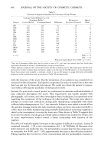
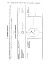
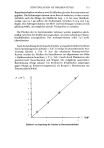
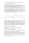
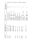
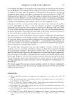
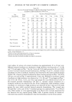
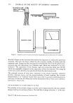
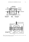
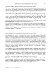
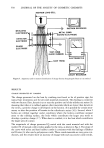
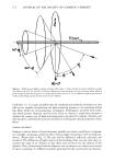
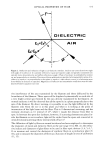
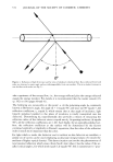
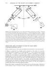
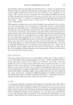
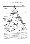
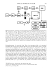
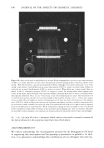
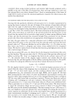
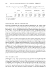
578 JOURNAL OF THE SOCIETY OF COSMETIC CHEMISTS Figure 6. Recording goniophotometer. W is 30-W tungsten-filament bulb which sends light to condensing lens C. Dichroic heat filter F• reflects long wave radiation (•. 700 nm) and transmits rays with •. 700 nm. S• and S2 are slits, O• and O2 are achromatic doublet objective lenses of 2 collimators, P• and P2 are rotatable Polaroid discs, and oq (equals 0, angle of incidence) and oz2 (angle of observation) are values for angles read off graduated arcs of instrument. HF designates planar array of hair fibers, F2 consists of 1 or more neutral density filters employed to adjust magnitude of signal. D contains detector, A is amplifier, and R is strip chart recorder. Basic instrument was made by Zeiss (Model GP-2) while mechanization and other alterations were carried out by Clairol. Slits provided have angular widths of 0.25, 0.5, and 1.0 ø. Normally, we employ 1 ø slits in both telescopes and find angular resolution to be adequate for work we do with hair. With 0.25 ø slits and light specularly reflected from polished black glass, half-intensity width of peak is 0.25 ø and full width of base is 0.50 ø REFLECTION AND SCATTERING OF LIGHT BY HAIR FIBERS GONIOPHOTOMETER CURVES EFFECTS ATTRIBUTABLE TO THE SCALES AND REFLECTIONS FROM FRONT AND REAR SURFACES In Figure 4 is depicted a ray of light incident obliquely on the surface of a taut hori- zontal fiber which is assumed to be ideal optically, i.e., it has a smooth external cylin- drical surface, a circular cross-section, and is colorless, transparent, and optically isotropic. For rays incident in a principal plane which is vertical and bisects the fiber longitudinally, it can be seen that we would anticipate reflection from the front face (near side) and from the rear face (far side), that all the reflected rays in both sets (near side and far side) would be parallel to one another, and that the angle of reflection would be equal and opposite to the angle of incidence, both being measured relative to the perpendicular to the axis of the fiber. Such is found to be the case with glass or synthetic fibers which sometimes approach ideality. Human hairs depart considerably from the ideal, and one principal point of departure is the existence of up to 10 layers of scales (cuticle) which cover the fiber, each layer

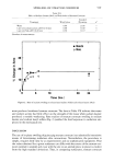
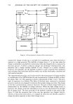
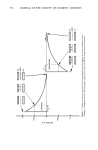
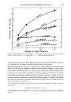
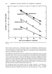
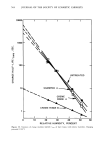
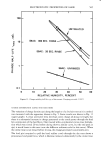
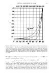
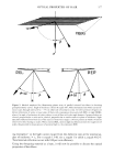
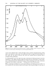
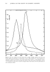
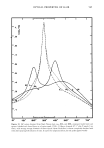
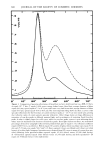
OPTICAL PROPERTIES OF HAIR 579 possessing a radial thickness of -0.5 /am. It is the presence of the scales which enhances the difficulty in measuring the light reflected by the external surfaces of hair fibers. In Fig. 5 is shown in elementary fashion a parallel beam of white light, coming from the lower right, illuminating a planar array of hair fibers held under slight tension, parallel to one another and oriented with all their root ends either to the right or to the left. The intensity of the light, which is specularly reflected and scattered by the hair fibers, is detected by suitable means at various angles in the plane of incidence, and recorded on a strip chart recorder. Such a device is known as a goniophotometer a rudimentary diagram of the instrument appears in Fig. 6 whose caption contains the necessary explanatory material. While maintaining the angle of incidence constant at, say, +30 ø relative to the perpendicular to the plane of the sample, the other collimator (provided with a detector) was scanned from 0 to -75 ø from the perpendicular reference line, and the intensity of the light detected was recorded as a function of the angle of observation. The array of fibers was 25 cm long x 25 mm wide, and the central fiber of the array was in the plane occupied by the optic axes of the two collimators. (Details regarding the instrumentation will be found in Appendix I.) In Fig. 7 we see, much reduced in size, goniophotometer (GP) curves typical of those obtained with root ends left (REL) or root ends right (RER) according to the diagram in Fig. 5. To emphasize specular reflection, Polaroids were used in front of each collima- tor lens in the configuration we designate es es with •, the electric vector, vibrating per- pendicular to the plane of incidence. There are 2 prominent features in each curve. In the case REL, there is a sharp peak at 35.2 ø and a weaker broader peak at -23 ø. The curve for the case RER is essentially the mirror image of the case REL except that the intensities are different. (The apparent discrepancy in intensities will be explained sub- sequently.) Den Beste and Moyer (15) published a curve of this type obtained using a goniophotometer with a "hair tress mounted in a special jig so that a straight flat surface was presented to an incident light beam at an angle of 30ø." (The angle of incidence relative to the normal to the plane of the sample was 60ø.) The resolution manifested by their curve was low because of the multiplicity of fibers employed. The brief state- ments made by them on page 600 of their paper were correct, but they did not go further into the optical aspects of the case because they were interested primarily in us- ing the areas under the diffuse peaks to measure the X, Y, and Z chromaticity values for various samples of hair. Returning to Fig. 7, if we replace the detector in the GP by the human eye, we find that the strong sharp peak is white light, whereas the light associated with the diffuse peak is the color of the hair. If the fibers had no scales, we would anticipate finding a single peak at 30 ø but there is none there. For the cases REL and RER, we calculate the dis- placements of the strong sharp peaks from the 30 ø position and find each of them to be 5.2 ø, which we divide by 2 to get 2.6 ø. This angle we shall designate as 0 and shall assume it to be the angle of inclination of the scales to the axes of the fibers. In addi- tion, because this is white light, we assume the sharp peak is attributable to direct specular reflection from the air-cuticle interfaces on the front faces or near sides of the fibers, i.e., the faces initially encountered by the incident light. Next, using optically flat black paint (3M Nextel Brand Velvet Coating, 101-C10 Black) the far sides of the same set of mounted fibers were spray painted using a tech- nique which avoided getting paint on the near sides. After running the GP curves of the blackened fibers, it was found that the weak diffuse peak had disappeared, and only
Purchased for the exclusive use of nofirst nolast (unknown)
From: SCC Media Library & Resource Center (library.scconline.org)